Do you have a question about the Honeywell ADEMCO VISTA SERIES VISTA-21iP and is the answer not in the manual?
| Partitions | 2 |
|---|---|
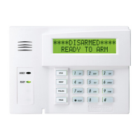
| Keypads Supported | Up to 8 |
| Control Panel Type | Hybrid |
| User Codes | 48 |
| Communication | IP |
| Wireless Zones | 40 |
| Keypad Zones | 8 keypad zones |
| Power Supply | 16.5VAC |
| Backup Battery | 12VDC, 4AH or 7AH |
| Operating Temperature | 0°C to 49°C (32°F to 120°F) |
| Humidity | Up to 93% non-condensing |
Guidance on placing smoke/heat detectors based on NFPA standards for optimal fire detection.
Guidelines for sensor placement for effective burglary detection and importance of radio backup.
Specifies system compatibility with microprocessor version 3.13 or higher.
Discusses SIA compliance for false alarm reduction for VISTA-21iPSIA and VISTA-21iP.
Lists key features like partitions, zones, security codes, schedules, and macros.
Details addressable keypads, zone expanders, wireless receivers, and other modules.
Crucial notes for installers regarding addressing, power-up, relays, function keys, and paging.
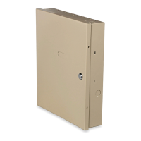
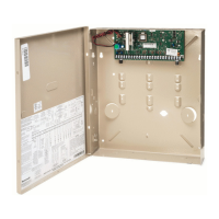
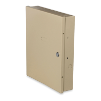
Instructions for mounting the cabinet and securing the PC board.
Steps for mounting the PC board and RF receiver module within the cabinet.
Table listing current draw for various devices for power budgeting.
Explains battery requirements for 24-hour standby and fire signaling.
Details wiring and specifications for the 1361 transformer.
Wiring instructions for the 1361X10 transformer used with Powerline Carrier devices.
Steps for connecting the backup battery to the control board.
Explains how the battery saver feature works to protect the battery.
Discusses the need for and methods of establishing an earth ground connection.
Instructions for connecting a sounder, including supervision and resistor placement.
Details supervision setup for sounders, including EOL resistor and programming.
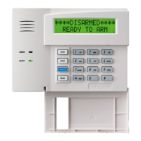
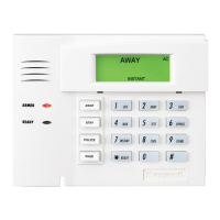
Guides on connecting keypads and addressable devices to keypad terminals.
Instructions for using a supplementary power supply for keypads when aux power is insufficient.
Instructions for connecting normally open and normally closed zones with EOLRs.
Guidelines for using double-balanced zones for burglary protection, noting fire zone restrictions.
Explanation of zone doubling feature and its wiring and usage constraints.
Instructions for connecting 2-wire and 4-wire smoke detectors, including power reset.
Lists compatible ADEMCO 5800 series wireless receivers and their zone capacities.
Steps for setting device address, mounting, and wiring the RF receiver.
Configuration options and placement advice for RF receivers to ensure optimal reception.
Wiring diagrams and steps for connecting a 4146 keyswitch to a zone.
UL requirements, usage restrictions, and programming for keyswitch zones.
Mounting, connecting, and addressing 4204/4229 relay modules and their supervision.
Installation of powerline carrier devices and use of 1361X10 transformer for home automation.
Connects incoming phone line and handset wiring to the control panel via RJ31X jack.
Compatibility, wiring, and connection of the 4286 phone module for voice communication.
Troubleshooting tips for issues with touch tone production and phone module connection.
Summary of AVS system installation, mounting, and wiring to the control.
Connects AVS base unit to control's ECP terminals and sets DIP switches.
Overview of the VISTA-GSM4G module for cellular communication and internet features.
Step-by-step instructions for physically mounting the VISTA-GSM4G module onto the control board.
General information about system programming methods and requirements.
Lists and describes various programming modes like Data Field, *56, *57, etc.
Steps for accessing programming mode from a keypad.
Explains tasks within data field programming, like entering data and reviewing fields.
Explains the purpose of data field programming and how to start.
Details system setup fields for installer code, quick arm, RF jam, bypass, and house ID.
Defines custom zone type 90 by selecting options for response and behavior.
Assigns Contact ID report codes for alarms and troubles for zone type 90.
Defines custom zone type 91 by selecting options for response and behavior.
Assigns Contact ID report codes for alarms and troubles for zone type 91.
Explains programming zones and partitions, including common zones.
Overview of programming zones, types, report codes, and RF transmitters.
Step-by-step guide to programming zones and confirming transmitters.
Steps to map output devices and create output definitions.
Assigns relay/Powerline Carrier addresses and maps outputs to device addresses.
How the system communicates alarms to the central station via handshake and kissoff.
Details supported handshake/kissoff frequencies and report formats.
Outlines essential tests after installation: System Test, Dialer Test, Go/No Go, RF Sniffer, Battery Tests.
Procedure for performing a walk test to check zone response and readiness.
Verifies that all wireless transmitters are programmed correctly.
Lists physical, electrical, and communication specifications for the control.
Lists compatible keypads, receivers, expanders, modules, and communication devices.
FCC Class B digital device statement and measures to correct interference.
IC statements regarding harmful interference and device acceptance.
FCC Part 68 compliance for telephone interface, USOC jack, and hearing aid compatibility.
IC notice on certified equipment, connection permissibility, and user protection.
Discusses system limitations regarding intruders, power, wireless signals, smoke detectors, and motion detectors.