Do you have a question about the Honeywell BENDIX/KING KY 96A and is the answer not in the manual?
Provides an overview of the manual's content and the transceiver's characteristics.
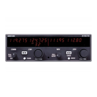
Details the five electrical sections of the transceivers and operational differences.
Lists key specifications including TSO compliance, power, and frequency range.
Details various KY 96A and KY 97A configurations and supplied components.
Lists essential accessories like antennas and cables not included with the unit.
Outlines FCC licensing and operator permit necessities for transmitter use.
Explains on-condition maintenance and the absence of periodic service requirements.
Provides suggestions and factors for satisfactory equipment performance during installation.
Details procedures for unpacking and inspecting the equipment for shipping damage.
Covers mounting, cooling, antenna, and cable harness installation procedures.
Recommends flight tests and checks for proper operation and cable interference.
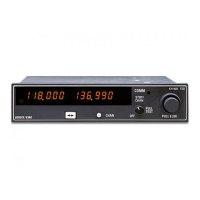
Steps to power on the unit, including squelch override and audio level adjustment.
Explains the TX indicator that appears when the transceiver is transmitting.
Details frequency, channel, program, and direct tune modes for operating the transceiver.
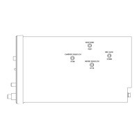
Describes how to transfer frequencies remotely using specific connector pins.
Explains how to increment channels remotely via specific connector pins.
Details how dim select affects display backlighting based on aircraft voltage.
| Brand | Honeywell |
|---|---|
| Model | BENDIX/KING KY 96A |
| Category | Transceiver |
| Language | English |