EasyManua.ls Logo

Honeywell XK516D1 User Manual

Honeywell XK516D1
300 pages
To Next Page IconTo Next Page
Page #1 background imageLoading...
Page #1 background image
Honeywell
I.B. 1516A Page T-1/T-2
May 5/97
Rev. 3: Oct 25/02
23-12-01
Component Maintenance Manual
XK516D1 HF Transceiver
Part Number
964-0452-001
964-0452-002
964-0452-011
964-0452-012
964-0452-022
DOCUMENT NO. 012-0693-001
Honeywell CAGE Code 97896

Table of Contents

Question and Answer IconNeed help?

Do you have a question about the Honeywell XK516D1 and is the answer not in the manual?

Honeywell XK516D1 Specifications

General IconGeneral
BrandHoneywell
ModelXK516D1
CategoryTransceiver
LanguageEnglish

Summary

Component Maintenance Manual

XK516D1 HF Transceiver

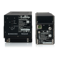
Manual for the XK516D1 HF Transceiver.

RECORD OF REVISIONS

RECORD OF TEMPORARY REVISIONS

SERVICE BULLETIN LIST

INTRODUCTION

ABBREVIATIONS AND ACRONYMS

REVISION 3 DATED Oct 25/02 HIGHLIGHTS

DESCRIPTION AND OPERATION

B. Electrical

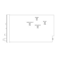
Details on the electrical aspects and connections of the transceiver.

C. Equipment Specifications

Technical specifications of the XK516D1 HF Transceiver.

D. Operation of XK516D1 in Voice Mode

Instructions for operating the transceiver in voice mode.

E. Operation of XK516D1 in HF Data Link Mode

Instructions for operating the transceiver in HF data link mode.

THEORY OF OPERATION

A. General

General description of the transceiver's operational principles.

B. Simplified Theory of Operation

Simplified explanation of the transceiver's operational theory.

(7) Controller D, A8, and Interface D, A9

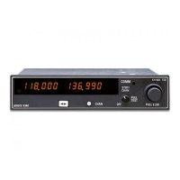
Description of controller and interface modules.

(a) Controller D, A8

Detailed description of the Controller D module.

C. Detailed Theory of Operation

(1) Receiver/Exciter, A1

Detailed theory of operation for the Receiver/Exciter module.

(a) Synthesizer

Theory of operation for the synthesizer module.

2 Loop 2

Description of synthesizer loop 2 operation.

4 DDS (digital direct synthesis)

Theory of operation for digital direct synthesis.

5 Loop 3

2 IF Processor, A12

3 Functional Description SSB Receive Mode

Description of SSB receive mode functionality.

4 Functional Description AM Receive Mode

Description of AM receive mode functionality.

5 SELCAL Reception

Description of SELCAL reception functionality.

(c) Transmission Section

Description of the transmission section's operation.

1 IF Processor, A12

2 Functional Description SSB Transmission Mode

Description of SSB transmission mode functionality.

(b) Amplifier Control, A33

1 Introduction

Introduction to Amplifier Control functions.

2 Data Bus Controller, A8 —> Amplifier Control, A33

Data bus control for Amplifier Control.

4 Control Branches

Description of control branches within Amplifier Control.

5 ALC Amplifier

6 Monitoring, CM, BIT

(4) Power Supply, A4

(a) Regulator Board, A41

Description of the Regulator Board.

2 Rectifiers and series regulators

Description of rectifiers and series regulators.

3 Continuous monitoring, CM

Controller D, A8, and Interface D, A9

(a) Controller D, A8

Description of the Controller D module.

1 Processor, D11

Description of the processor unit.

5 USART

a Test interface

Description of the test interface for commands.

b Coupler interface

Description of the coupler interface.

6 Module bus Interface

Description of the module bus interface.

(b) Interface D, A9

1 ARINC input

Description of ARINC input functionality.

(8) HF Modem, A10

(9) ON/OFF Module, A15

TESTING AND FAULT ISOLATION

1. Introduction

Information and instructions for testing and fault isolation.

2. Test Equipment

List of required test equipment.

3. Test Conditions

Laboratory conditions for performing tests.

4. Power Requirements

Power source requirements for the transceiver and test equipment.

5. Automated Test Equipment (ATE) Setup

Setup procedures for Automated Test Equipment.

A. Software Installation

B. ATP Software Installation

C. CFDS Software Installation

6. HF Transceiver Test Setup

7. HF Transceiver ATP

Fault Isolation

A. General

General information for fault isolation of the HF Transceiver.

B. Methods of Fault Isolation

Methods used for fault isolation.

C. Fault Isolation Aids

Aids used in fault isolation.

(1) BIT

Explanation of Built-In Test (BIT) function.

(2) Schematic Diagrams

Availability of schematic diagrams for fault isolation.

D. BITE

ï LAST LEG REPORT

LRU faults stored during the last flight leg.

ï PREVIOUS LEGS REPORT

LRU faults stored during previous flight legs.

ï GROUND REPORT

LRU faults stored during ground tests.

ï TROUBLESHOOTING

Supplementary information on fault messages.

ï LRU IDENTIFICATION

Part number, software, and serial number of LRUs.

ï TEST

Manual initiation of the power-up self-test.

E. Manually-Initiated Test/Power Up Test

F. Basic Voltage Test Procedure

G. Transceiver Fault Isolation Chart

H. Procedure to Verify Failed Frequency with the CFDS Function

DISASSEMBLY

1. General

General instructions for disassembling the transceiver.

2. Disassembly Techniques

Techniques for disassembling assemblies and parts.

3. XK516D1 Transceiver (IPL Fig. 1)

Steps for disassembling the XK516D1 Transceiver.

CLEANING

1. General

Materials used for cleaning assemblies and parts.

2. Transceiver Procedures

Procedures for cleaning the transceiver.

CHECK

1. General

General guidelines for visual inspection.

2. General Checks

General visual checks for parts and components.

3. Specific Checks

Specific inspection points for various parts.

REPAIR

1. General

General guidelines for repair procedures.

2. Circuit Card Assemblies (CCA)

Procedures for repairing circuit card assemblies.

3. Conformal Coating

Procedures for applying conformal coating.

4. Solder

Procedures for soldering and desoldering.

7. Transceiver Special Requirements

ASSEMBLY (INCLUDING STORAGE)

1. General

General guidelines for assembly and storage.

2. Transceiver Assembly (Ref. IPL Fig. 1)

Steps for assembling the transceiver.

FITS AND CLEARANCES

SPECIAL TOOLS, FIXTURES, AND EQUIPMENT

ILLUSTRATED PARTS LIST

1. Introduction

Introduction to the Illustrated Parts List (IPL).

2. Definitions

Glossary of terms used in the IPL.

EQUIPMENT DESIGNATOR INDEX

NUMERICAL INDEX

Related product manuals