Honeywell
COMPONENT MAINTENANCE MANUAL
PART NUMBER 964-0452
I.B.1516A
Mar 30/01
23-12-01
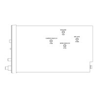
Block Diagram (Simplified), Transceiver
Figure 5
When receiving, the RF signal is down-converted by means of 2 mixer stages to the second
IF of 25kHz. This IF signal is digitized and undergoes further conditioning in the signal pro-
cessor. The additional functions, such as filtering, demodulation, and control are achieved by
means of software and appropriate algorithms. The processed signal subsequently under-
goes analog conversion again, and is output to the appropriate audio interface (voice audio
output to MP-1D/1E, SELCAL audio output to MP-3C/3D, external data output to MP-1F/1G,
internal HFDL data received audio to Modem, A10).
All external interfaces are passed through EMC Filter, A7, to suppress spurious signals.
The internal BITE system of the Transceiver detects a defective LRU by means of continuous
monitoring, and localizes the fault down to functional units on modules (SRUs). In addition,
Page 13
 Loading...