INSTALLATION MANUAL
89000007
Page 2-8
15 Nov 2013
© Honeywell International Inc. Do not copy without express permission of Honeywell.
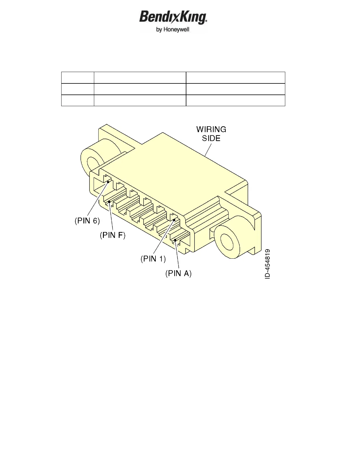
Table 2-2. Secondary Interface Pinout Locations (Cont)
Pin Signal Direction
E ARINC Traffic B Output
F ARINC Traffic A Output
Figure 2-3. Secondary Interface Pinout Locations
2.5.3 Orientation Diagram
To assist in connector orientation, the following example shows a typical set
of connections. Figure 2-4 shows the expected connector positions when
viewed from the transponder side of the tray, looking into the tray from the
front. In the example shown the aircraft uses a 14-volt lighting bus, a parallel
altitude encoder, a DME with simple suppression output, a GPS with serial
position output, and a simple lamp for the altitude alerter. This example is
representative of a simple fixed gear 14-volt aircraft.