EasyManua.ls Logo

Honeywell Braukmann T104F - User Manual

Honeywell Braukmann T104F
6 pages
Print Icon
To Next Page IconTo Next Page
Loading...
1 62-3047
C. H. • 12-94 • ©Honeywell Inc. 1994 • Form Number 62-3047
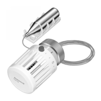
T104F
Thermostatic Control
The T104F Thermostatic Control is used with a V110
Valve Body to control radiators, convectors, baseboard
heating units, or other heating units with standard capacity
requirements. The control is self-powered and requires no
electrical connection. The T100A includes a setpoint dial
and valve actuator, connected by a capillary tube to a sensor.
The T104F Control attaches to the valve body by threaded
connections and may be mounted at any angle. Install the
remote sensor beneath the heating coils in the cold air re-
turn, or on a nearby wall where the air flow is not restricted.
The setpoint dial has reference marks (1-6). The control
has a low limit of 43°F (6°C) when the dial is turned fully
clockwise to the frost protection mark*. The red button
indicates the 68°F (20°C) setpoint limit. Higher settings may
be made by holding in the button while turning. The thermo-
static sensor is protected by a safety spring against tempera-
tures to 125°F (52°C).
M9730
2
3
Specifications
MATERIALS OF CONSTRUCTION:
Body: Industrial grade plastics with low thermal
conductivity.
Fastening Ring: Plated brass.
Internal Parts: Brass thermostat capsule, other metals.
TEMPERATURE RANGE: 43° to 79°F (6° to 26 °C).
MAX. SENSOR TEMPERATURE: 125°F (52°C).
MAX. OVERALL DIMENSIONS: 2-1/8 in. (54 mm) wide,
3-5/16 in. (84 mm) long. See Fig. 1.
CAPILLARY LENGTH: 6 ft. 8 in. (2 m).
TEMPERATURE SETTINGS:
These are the setpoint temperatures, which correspond
to the setpoint dial reference marks, under ideal conditions.
Factors affecting the temperature at the sensor vary for each
installation. It may be necessary to adjust the setpoint
higher or lower to obtain the desired space temperature.
Fig. 1—T104F dimensions in in. (mm).
AVAILABLE VALVE BODIES:
See Fig. 2.
Temperature 0 *123456
°F Off 43 46 54 61 68 73 79
°C Off 6 8 12 16 20 23 26
3 5/16
(84)
MAX.
2 1/8 (54)
M9731

Questions and Answers

  • W
    wlongJul 31, 2025
    Why is my Honeywell Thermostat overheating?
    • D
      Derek DelacruzJul 31, 2025
      Overheating can occur in your Honeywell Thermostat if the sensor is improperly located; try changing its position or the control type. Ensure the control is correctly installed by setting the bosses in the grooves and tightening the knurled ring to the valve body. If the capillary tube is broken, kinked, or bent sharply, the control should be replaced. Dirt or scale under the seat preventing tight shutoff can also cause overheating; remove the control, flush away debris, and reinstall. For hot water systems, excessive differential pressure can force the valve open; consider installing a differential pressure regulator. Defective steam traps should be repaired or replaced. Also, ensure that the flow through the valve is in the correct direction.
  • R
    Rita WallsAug 20, 2025
    What to do if Honeywell Thermostat is chattering or knocking?
    • W
      William HillAug 20, 2025
      Chattering or knocking in your Honeywell Thermostat can occur due to several reasons. Ensure that the flow through the valve is in the correct direction, matching the arrow on the valve body. If there's a vacuum in the system, check traps and vents for steam systems, and the expansion tank operation and location for hot water systems. Excessive differential pressure can also cause this issue, requiring the installation of a differential pressure regulator. Binding of piping can be another cause, so ensure there is adequate space for piping.
  • M
    Michael JohnsonNov 8, 2025
    How to fix underheating Honeywell Braukmann T104F Thermostat?
    • H
      Harold MoralesNov 8, 2025
      Underheating in your Honeywell Thermostat can be caused by several factors. The sensor might be in the wrong location, in which case you should change its location or the control type. If excess capillary tube is coiled above or too near the heat source, coil it below or away from the heat source. Ensure flow through the valve is in the correct direction, matching the arrow on the valve body. Inadequate system temperature or pressure requires checking the boiler's operating and limiting controls, as well as the circulating pump and isolating valves. Defective steam traps should be repaired or replaced. An air lock in the hot water system can be resolved by fully opening the valve or installing vents. Scale or debris blocking flow requires flushing the system, avoiding oil-based additives, ...

Summary

Specifications

Materials of Construction

Details on industrial grade plastics, plated brass fastening ring, and internal metal parts.

Temperature Settings

Corresponds setpoint dial marks to actual temperatures under ideal conditions.

Installation

Settings and Calibration

Setting the Limit

Procedure to set a different low or high limit or locking temperature using a pin.

Locking the Control at a Single Temperature

Recalibrate T104 F Control

Troubleshooting

Honeywell Braukmann T104F Specifications

General IconGeneral
MountingWall Mount
StagesSingle Stage
Temperature ControlMechanical
Switch ActionSingle Pole, Single Throw (SPST)
CompatibilityHeating or Cooling

Related product manuals