CT41A HEATING/COOLING THERMOSTAT
3 69-0788-2
❑ Push excess wire back into wall and plug hole with
nonflammable insulation to prevent drafts from
affecting thermostat operation.
❑ Remove thermostat cover by pulling outward on right
edge of cover until it snaps free of the thermostat
base.
❑ Fasten thermostat to wall or vertical outlet box with a
screw through the top mounting hole. See Fig. 2 for
hole location.
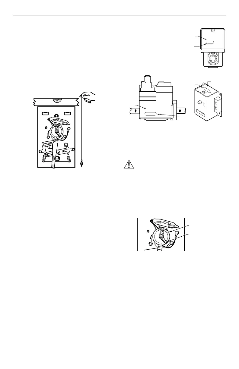
❑ Place a bubble level or plumb line against the
thermostat to find the level position. See Fig. 5. Start a
screw in the center of the bottom mounting hole.
(Move the temperature setting lever, if necessary, to
uncover the mounting hole.)
Fig. 5. Level thermostat.
❑ Recheck for level positioning and firmly tighten both
mounting screws.
❑ Be sure you have the current draw anticipator setting
for your system. This is the number you wrote in the
box in step 2 Remove Old Thermostat section. If you
could not find the current draw for step 2, look on your
primary control at the furnace. See Fig. 6. (The
primary control is usually a gas valve, zone valve, or a
relay or burner control box with the thermostat wires
connected to it. For electric heat, add the fan relay
current, usually 0.2A to 0.4A.)
Fig. 6. Locate your system current draw anticipator
setting.
❑ Set the heat anticipator indicator at the rating printed
on the primary control. See Fig. 7.
CAUTION
Heat Anticipator Hazard.
Setting heat anticipator too low can cause
anticipator burnout.
Set heat anticipator at recommended rating to
avoid shorting out your valve or control and
prevent burnout of your heat anticipator.
Fig. 7. Set heat anticipator indicator to match your
primary control rating.
❑ Press thermostat cover firmly onto the mounting clips.
See Fig. 2.
.18
.2
.25
3
.5
.7
.9
BUBBLE LEVEL
PLUMB
LINE
PLUMB
BOB OR
WEIGH
V8043E 1004 4
24V 50/60CY
.32 AMP
@ 60CY
8406
24 Vac 50/60 Hz
0.4 AMP
30 VAC
0.2 AMP
T
F
T
F
OIL BURNER CONTROL
SHOWS
CURRENT
DRAW
SHOWS
VOLTAGE
RATING
M6116B
ROM MAIN
UEL SUPPLY
SHOWS
VOLTAGE
RATING
TO
BURNER
SHOWS
ANTICIPATOR
SETTING
TYPICAL GAS VALVE
ZONE VALVE
SHOWS
VOLTAGE
RATING
SHOWS
ANTICIPATOR
SETTING
.18
.2
.25
3
.5
.7
.9
SCALEPLATE
M378
ADJUSTABLE
HEAT
ANTICIPATOR
SETTING LEVE
 Loading...