CX Series
ISSUE 4 PK 88136
2. Turn cam wheel to be adjusted to desired
position. Each notch on the wheel represents a
change in operation point of 0,116 mm (.0045
in.). Moving the cam wheel in the direction away
from the base housing advances the operate
point. Pretravel decreases and overtravel
thereby increases. When positioning cams, be
sure the cam follower is allowed to utilize the full
rise of the cam. This is required to provide
adequate overtravel and release travel of the
basic switches.
IMPORTANT: Do not use the set screw in the
cam follower to adjust travel characteristics.
3. Release cam wheel.
4. Release cam follower.
To Adjust Rotary Types:
1. Lift cam follower.
2. Move cam wheel axially to disengage teeth on
wheel from teeth on shaft disc.
3. Turn cam wheel to desired position. Turning in
direction of shaft rotation advances operate
point. Pretravel decreases and overtravel
thereby increases. Each notch on the cam
wheel represents an operating point change of
7°20'. The symbols on the cam wheel simplify
changing rotation from clockwise to
counterclockwise to center neutral, or vise versa.
If the switch operates on clockwise and
counterclockwise rotation, the pointer on the cam
follower lines up with symbol
or symbol on
the cam wheel. When symbol
lines up,
pretravel of 15° max. is obtained. When symbol
lines up, 80° max., pretravel is obtained.
Operation is in the direction of the inclined
surface of the symbol when
or lines up with
the pointer on the cam follower.
4. When cam wheel has been rotated to desired
location, release cam wheel to engage with
mating shaft disc.
5. Release cam follower
CX Wiring Methods
Honeywell recommends that conduit be installed
per NEC articles 501-4 and 501-5.
REPLACEMENT PARTS
Replacement switch assemblies consist of the
components subject to mechanical or electrical
wear. They include basic switches, cam wheels,
cam followers, and springs. The assemblies are
factory adjusted to have the same operating
characteristics as new complete switches.
How to Order
Catalog listings for complete switches can be
converted to replacement switch assembly catalog
listings as follows:
Momentary action rotary or plunger actuated
switches with shaft or plunger restoring force: To
order a replacement assembly, change the first digit
in the catalog listing for a complete switch to 9 for
rotary switches or to 10 for plunger switches.
For example, the replacement switch assembly
for a 12CX5 rotary switch = 92CX5. The
replacement switch assembly for a 36CX2 plunger
switch = 106CX2.
Maintained action rotary switches without shaft
restoring force: To order a replacement assembly,
change the first digit to a 9 and drop the first digit
following the letters CX.
Example: 12CX12=92CX2
Printed circuit board (includes potentiometer)
for 4-20 mA current output CX switches: 15PA261-
CX.
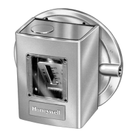
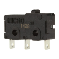
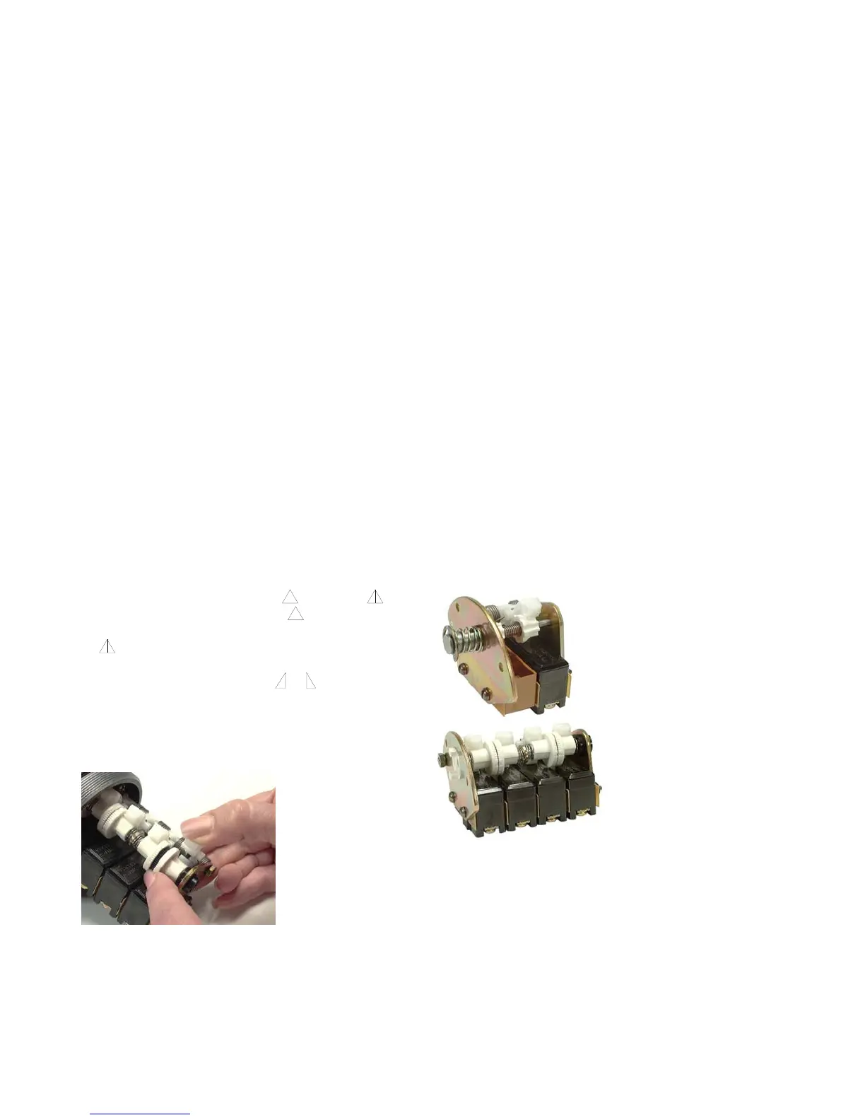
Plunger Switch
Assembly
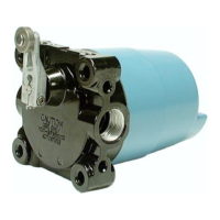
Rotary Switch
Assembly
2 Honeywell • Sensing and Control
 Loading...