OPERATING INSTRUCTIONS
74-5069
DeltaNet FS90 Operating Instructions
SYSTEM OPERATION
A normally functioning DeltaNet Fire & Security System is indicated
by the green RUN and green POWER LEDs on the powered Control
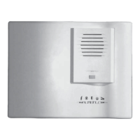
Board. If a Communication Board is installed, the Communication
Board red TRANSMIT and RECEIVE LEDs blink as data is
communicated.
Power Supply Supervision
The power supply circuits for the DeltaNet FS90 Fire & Security
system are monitored for Integrity. Trouble conditions in these circuits
are indicated by Low Battery (yellow) and Power (green) LEDs on the
CA control board. In the normal, supervisory, condition, the yellow
Low Battery LED is off and the green Power LED is on. A trouble
condition in the power supply circuits is indicated when either the
green Power LED is blinking or the yellow Low Battery LED is on. If
this occurs, contact a service technician to determine the nature of the
trouble condition by removing the batteries from the system and
testing their condition. With the batteries out of the system, proper
functioning of the power supply, battery changer and battery
supervision circuits should be verified. Any faulty component must be
replaced.
Modes of Operation
The DeltaNet Fire & Security System can operate independently
(Stand-Alone Mode) or as a Data Gathering Panel (DGP) in a higher-
order system (DGP Mode). DGP Mode is in effect when a
Communication Board is plugged into the Motherboard and active
communication takes place. If communication fails, the system
operates in Stand-Alone Mode.
LJ Communication/Display Board Switch
When the LJ Board MULTIPLE ALARM-TROUBLE LED is on,
multiple abnormal conditions (alarm, trouble, prealarm) exist on AE
Board loops. The LJ Board displays one address at a time, beginning
automatically with the address of the highest-priority device.
An address remains displayed until a new, higher priority device goes
into an abnormal condition or until the PREVIOUS/NEXT switch is
pushed. Use the PREVIOUS/NEXT switch to display other addresses
as follows.
PRINTER/DISPLAY ASSEMBLY AND LH INTERFACE BOARD
OPERATING INSTRUCTIONS
The two front Printer/Display Assembly switches are:
— Printer On-Line Switch with integral LED.
— Paper Advance Switch.
LH Interface Board switches are:
— ACK—UP to acknowledge indicated point in LCD display.
— ALL PT/ALM SUM—UP to request All Point Log; DOWN to
request Alarm Summary Log.
— PREVIOUS/NEXT—UP to revert LCD display to former point;
DOWN to advance LCD display to subsequent point.
FRONT PANEL SWITCHES/LEDS
Control Board Switches
ACKNOWLEDGE
— Pushing the ACKNOWLEDGE switch silences the local audible
and changes blinking LEDs to ON. The ACKNOWLEDGE switch
does not affect indicating zone outputs and does not silence alarm
signals. Pushing the ACKNOWLEDGE switch acknowledges all
alarms present in the panel.
— If the panel is a DGP, the ACKNOWLEDGE switch does not
function when the DGP is communicating with the higher-order
system. The ACKNOWLEDGE switch becomes functional when
communication is broken.
SILENCE
Pushing the SILENCE switch does the following:
— Silences devices connected to indicating zones.
— Silences devices connected to Control Modules with indicating
characteristic set.
— Silences the local audible.
— Turns on the Control Board SILENCE LED.
— Changes blinking LEDs to on.
RESET
Pushing the RESET switch removes power to all initiating zones for
fifteen seconds and sends out a fifteen-second reset signal that
returns all input-zone status indicators to normal. After reset, zones
that return to alarm or trouble are annunciated as new alarms or
troubles.
PANEL TEST
Performing a Panel Test reveals whether all boards are controlled by
the panel microprocessor. Pushing the PANEL TEST switch turns on
all LEDs, except Communication Board LEDs and turns on the local
audible. A Panel Test does not interrupt alarms or troubles reporting in
the system.
Pushing the PANEL TEST switch turns on all LJ Communication/
Display Board LEDs and causes the LJ Board to display the address
8888.
Pushing the MANUAL EVACUATION switch does the following:
— Turns on all indicating zones.
— Turns on all AE Board Control Modules that have the indicating
characteristic set during system setup.
— Causes a common alarm indication.
— Causes the local audible to pulse.
Manual evacuation is terminated by pushing either the SILENCE
or the RESET switch.
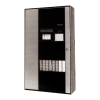
Honeywell DeltaNet FS90 Fire & Security System
Control Unit
LOCAL SERVICE REPRESENTATIVE
Name:
Address:
Phone:
Refer to Installation Instructions: Honeywell form no. 95-7421-3, issued 10-2007