Do you have a question about the Honeywell VARIODYN D1 Comprio and is the answer not in the manual?
Provides general information on the product's intended use and necessary operational warnings.
Information for qualified personnel and safety guidelines concerning fire alarm systems.
Explains safety symbols and warnings for user protection and damage prevention.
Explains system naming based on region and relevant standards like DIN VDE 0833-4.
Defines operator responsibilities and system setup requirements for voice alarm systems.
Lists related documentation for system setup, installation, and configuration.
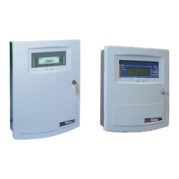
Details the functions and components of the compact control unit.
Describes the programmable buttons and microphone connections of the voice input station.
Illustrates how buttons can be assigned functions like pre-selection, announcement, and intercom.
Explains how collective messages are displayed and operated via LEDs and buttons.
Details the interface module for audio signals, control contacts, and related status LEDs.
Explains LED indicators for control contacts, DAL connections, and collective status.
Describes LED indications for amplifier channel status like 'not in use', 'ready', 'prelistened', 'fault'.
Explains LEDs for loudspeaker circuit usage (LINE RELAY).
Explains LEDs indicating faults in loudspeaker circuits.
Details LED status for the DAL BUS connections.
Details LED status for individual DAL channels.
Shows general status LEDs for ERROR, STANDALONE, POWER, and POWERFAIL.
Explains status for networking, power supply faults.
Describes the monitor button for prelistening and buzzer acknowledgement.
Describes LED indicators for channel errors, overload, and clipping.
Explains LEDs indicating detected audio signal levels for high and low frequencies.
Details status LEDs for power channels, system faults, battery/mains power, and CPU status.
Outlines requirements for HWS operator training and system readiness.
Covers inspection frequency, repair procedures, and annual maintenance tasks.
Details required tests for loudspeakers, room coverage, and backup measures, plus logbook requirements.
| Brand | Honeywell |
|---|---|
| Model | VARIODYN D1 Comprio |
| Category | Control Panel |
| Language | English |