10 Replacement Kit Instruction 43-DR-33-87 3/05
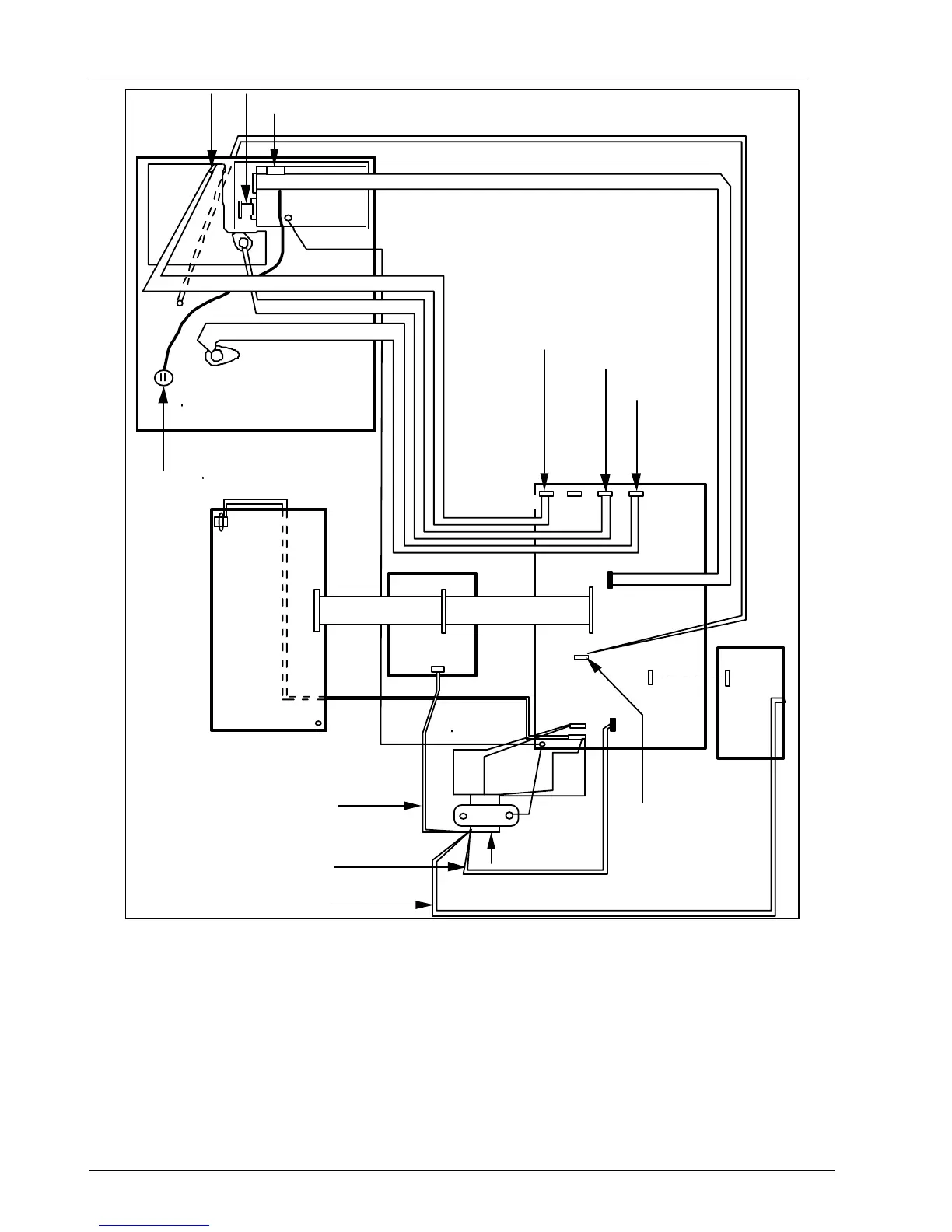
Mother board
J8
1
1
J2
7 cond.
cable
J13
1
1J1
4 cond.
cable
Chassis
ground
1
J14
Main
board
J15
J4
1
J2
Alarm/digital
inputs
J1
1
34 cond.
ribbon cable
30755119-001
J8
Chart Plate
Display
board
30755064-001, 20 conductor ribbon cable
4 conductor cable
4 conductor cable
4 conductor cable
2 wires (black)
Chassis ground
Pen
Motor
Chart motor
J5
J7
Optical sensor
Pen drive
Chart drive
11 1
Main transformer
9 position keyboard cableOptical sensor
assembly
J2
J3
2 wire
purple pair
2 wire
orange pair
Pen
stylus
output
1
Second
input
1
J3
2 wire
light
2 wire
gray pair
Light line to J1
J11
J3
Pen
stylus
1
30754982-001
30754982-001
Figure 4 DR4500 Truline Recorder (DR450T, DR450R, DR450W, DR450H) Internal Cabling Data
 Loading...