EasyManua.ls Logo

Honeywell Electronic Aquastat L7148F User Manual

Honeywell Electronic Aquastat L7148F
12 pages
To Next Page IconTo Next Page
Page #1 background imageLoading...
Page #1 background image
PRODUCT DATA
68- 0189- 2
® U.S. Registered Trademark
Copyright © 2001 Honeywell • All Rights Reserved
L7148F
Electronic Aquastat
®
Controller
GENERAL
The L7148F Electronic Aquastat
®
Controller is an immersion
type hydronic controller that provides high limit protection
and controls circulator, gas valve and optional vent damper
equipment. The complete L7148F system requires a sensor,
immersion well and transformer, all of which must be ordered
separately. See Table 1 for sensor specifications.
An external 120 Vac to 24 Vac transformer is required to
power the L7148F. For total external transformer VA
requirements, add the 10 VA requirement for the control,
gas valve load requirement (connections B1, B2), zone valve
connection requirement (see zone valve specifications), vent
damper requirement and VA requirement for any other
equipment. Total low voltage load must not exceed 4A.
FEATURES
Available with quick connect or AMP
®
plug
connections. T, TV and Z terminals are provided
in a terminal block with screw connections.
Vent damper plug optional.
Separate high limit control not required.
Software defined minimum/maximum limit settings.
External 120 Vac to 24 Vac transformer, ordered
separately, is field replaceable and upgradable.
Patented limit rated 209659A,B,C Sensors are
separately replaceable.
Communications port for future field added advanced
feature modules.
Flush mounted to sheet metal rather than spud
mounted to sensing well.
3/16 in. (5 mm) B1 quick connect and AMP plug
connections meet ANSI miswiring requirements.
UL353 Limit Controls approval for both U.S. and
Canada.
Meets UL 1998 Software Safety Standards.
Diagnostic LED to assist in system troubleshooting.
L7148F WITH QUICK CONNECTS
(SENSOR NOT INCLUDED)
L7148F WITH PLUG CONNECTIONS
(SENSOR NOT INCLUDED)
Contents
General ............................................................................. 1
Features ........................................................................... 1
Specifications ................................................................... 2
Ordering Information ........................................................ 2
Installation ........................................................................ 3
Adjustment ....................................................................... 5
Operation .......................................................................... 5
Checkout .......................................................................... 11
Troubleshooting ................................................................ 11
This is a legacy product document supported by
Resideo. This product is no longer manufactured.
Question and Answer IconNeed help?

Do you have a question about the Honeywell Electronic Aquastat L7148F and is the answer not in the manual?

Honeywell Electronic Aquastat L7148F Specifications

General IconGeneral
TypeElectronic Aquastat
ModelL7148F
Voltage120 VAC
Temperature Range100°F to 240°F (38°C to 116°C)
Control TypeOn/Off
Switch TypeSPDT
ApprovalsUL, CSA
DifferentialAdjustable 5°F to 30°F (3°C to 17°C)
MountingSurface
Sensor ElementLiquid-filled
Capillary Length6 ft (1.8 m)
Well Size1/2 in

Summary

General Information

Product Overview

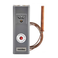
Immersion type hydronic controller for high limit protection and controls circulator, gas valve, and optional vent damper.

Key Product Features

Highlights advanced capabilities like software-defined limits, communications port, diagnostic LED, and compliance.

Product Specifications

Standard Models and Operating Ranges

Details models, high limit setpoint range, differential, voltage, and ambient temperature ratings.

Approvals and Standards

Lists UL, ANSI, and MSDS information relevant to the product's compliance and safety.

Compatible Accessories

Lists optional accessories like heat conductive compound, sensor clamp, and sensor spring for installation.

Installation Procedures

Installation Steps and Safety Warnings

Covers general installation steps, safety warnings for fire/explosion and electrical shock hazards.

Mounting and Sensor Installation

Details mounting procedures, sensor insertion into the well, and securing the well.

Wiring and Connections

Screw Terminal Connections

Step-by-step guide for stripping wires and securely connecting them to screw terminals.

Quick Connect and AMP Plug Wiring

Instructions for connecting quick connect terminals and AMP plugs to the L7148F control.

Operation and Control

Controller Operational States

Describes the three operational states: Normal, High-Limit, and Reset, and mode transitions.

High-Limit Functionality

Explains how the high-limit switch operates to shut off the burner when temperature exceeds the set point.

Sequence of Operations

Details burner and circulator output states based on thermostat input and current operation mode.

System Checkout

Post-Installation System Check

Verifies proper installation, adjustment, and operation through system cycles.

Troubleshooting and Diagnostics

Diagnostic LED Indicator Codes

Explains LED codes for identifying system performance issues and potential error conditions.

Troubleshooting Flowchart

Provides a step-by-step flowchart for diagnosing system problems and identifying faulty components.

Related product manuals