EasyManuals Logo

Honeywell enCore FC1 User Manual

Honeywell enCore FC1
133 pages
To Next Page IconTo Next Page
To Previous Page IconTo Previous Page
Page #91 background imageLoading...
Page #91 background image
6 Assembly Instructions
enCore FC
Operating Instructions
Page 91 of 120
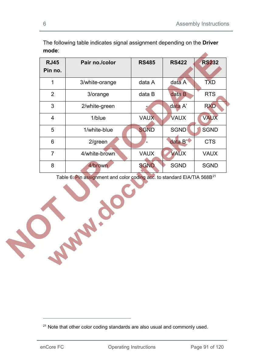
The following table indicates signal assignment depending on the Driver
mode:
RJ45
Pin no.
Pair no./color RS485 RS422 RS232
1 3/white-orange data A data A TXD
2 3/orange data B data B RTS
3 2/white-green - data A RXD
4 1/blue VAUX VAUX VAUX
5 1/white-blue SGND SGND SGND
6 2/green - data B CTS
7 4/white-brown VAUX VAUX VAUX
8 4/brown SGND SGND SGND
Table 6: Pin assignment and color coding acc. to standard EIA/TIA 568B
21
21
Note that other color coding standards are also usual and commonly used.

Table of Contents

Other manuals for Honeywell enCore FC1

Questions and Answers:

Question and Answer IconNeed help?

Do you have a question about the Honeywell enCore FC1 and is the answer not in the manual?

Honeywell enCore FC1 Specifications

General IconGeneral
BrandHoneywell
ModelenCore FC1
CategoryDesktop
LanguageEnglish

Related product manuals