DISTRIBUTED I/O
EN0B-0090GE51 R0802 10
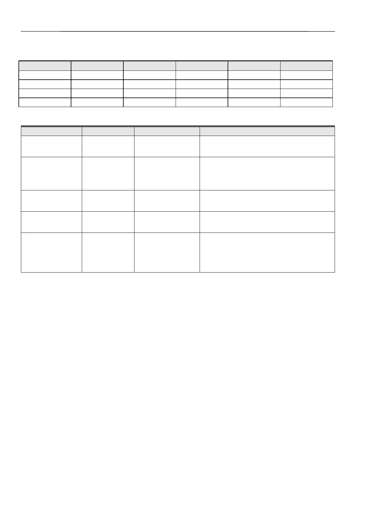
Table 7. Relation between physical state and logical status as defined by the point attribute NO/NC for the XFL523B
Contact position NO/NC attribute Logical status Input voltage LED switch on LED switch off
open NO 0 ≤ 2.5 V off green
closed NO 1 ≥ 5 V yellow red
open NC 1 ≤ 2.5 V yellow red
closed NC 0 ≥ 5 V off green
Table 8. LONMARK Object NVs for the XFL523B
NV Name Type Range Description
nvoDiValue SNVT_switch
Transmits the state of the input channel every time
there is a state change or if SCPTMaxSendTime in
the Node Object has expired.
nvoDiValueCnt SNVT_count
binary: 0, 1
totalizer: 0 to 65534
(65534 initial value)
Transmits the state of the input channel every time
there is a state change or if SCPTMaxSendTime in
the Node Object is expired. If configured as a
totalizer, this NV transmits the number of transitions
from 0 to 1.
UCPTSensorConfig
0 (not used)
1 = binary (default)
2 = totalizer
Specifies the setting for a sensor channel.
UCPTSendOnDelta SNVT_count 0 to 65535
Specifies the difference in totalizer count required
before a transmission of the value output of the
Sensor Object takes place.
SCPTDirection SNVT_state
Used to define the relation between the logical status
of the input and the state of the LED. One bit cor-
responds to one input channel (bit 4 = input channel
12, bit 15 (MSB) = input channel 1). If a bit is clear,
the LED for the channel will be 0=green and 1=red. If
the bit is set, then 0=red and 1=green.

 Loading...


