EasyManua.ls Logo

Honeywell Excel 5000 open XFL523B User Manual

Honeywell Excel 5000 open XFL523B
30 pages
To Next Page IconTo Next Page
Page #1 background imageLoading...
Page #1 background image
® U.S. Registered Trademark
Copyright © 2002 Honeywell Inc. • All Rights Reserved EN0B-0090GE51 R0802
74-2145-2
Distributed I/O
XFL521B, 522B,
523B, AND 524B MODULES
PRODUCT DATA
FEATURES
LONMARK™ compliant
2-wire LONWORKS
®
bus interface between controller
and I/O
No additional field terminals required
Usable with Excel 500 controllers in conjunction with
standard internal I/O modules
Automatic binding and commissioning to Excel 500
controllers when using CARE
Connector module with sliding bus connector
(eliminating the need to wire together neighboring
modules)
Fast connection due to spring clamp terminals
Module exchange during operation
Alarm in case of defective module
Mechanical coding prevents mismatching of modules
Power LED (L1, green) and L
ONWORKS service LED
(L2, red) on all electronics modules
Status LEDs for outputs and digital inputs
Optional manual override modules for analog and
digital output modules with feedback
XILON for wiring test
GENERAL
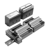
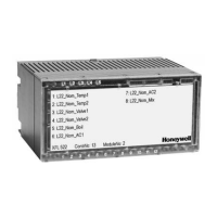
The XFL521B, 522B, 523B, and 524B modules are LONMARK
compliant digital and analog I/O modules which can be
installed at strategic locations within a building. These
modules convert sensor readings and provide output signals
used for operating actuators via L
ONWORKS standard network
variables (SNVTs). Each Distributed I/O module plugs into a
base terminal block allowing communication with controllers
via the built-in Echelon
®
LONWORKS bus interface. The ter-
minal block provides spring clamp terminals for easy connec-
tion of field cables from the various sensors and actuators.
The modular system allows Distributed I/O modules to be
removed from the system without disturbing other modules.
The module with terminal block mounts easily onto a DIN rail.
When using CARE, the Distributed I/O modules can be
automatically bound and commissioned to the Excel 500
CPU (XC5010C, XC5210C, XCL5010) and XL50. When the
modules are used by other controllers, provided plug-ins
permit the modules to be commissioned by CARE 4.0 or by
any LNS network management tool.
DESCRIPTION
These Distributed I/O modules use a Neuron® chip and an
FTT-10A free topology transceiver for communication on a
L
ONWORKS bus and comply with LONMARK Application Layer
Guidelines V3.2.
Table 1. Modules and accessories
Item Description
XFL521B Analog input module
XFL522B Analog output module
XFL523B Digital input module
XFL524B Digital output module
XSL511 LONWORKS connector module
XSL512 Manual terminal disconnect module
XSL513 Terminal block for XFL521x, 522x, 523x
XSL514 Terminal block for XFL524x
XFR522A Analog output manual override module
XFR524A Digital output manual override module
XAL-Code To prevent mismatching modules
XAL-Term Interface to the LONWORKS bus
209541B LonWorks bus termination modules
XAL 2 Cover release tool
XAL 1 Swivel label (for manual override modules)
Question and Answer IconNeed help?

Do you have a question about the Honeywell Excel 5000 open XFL523B and is the answer not in the manual?

Honeywell Excel 5000 open XFL523B Specifications

General IconGeneral
ModelXFL523B
CategoryI/O Systems
Accuracy±0.1% of full scale
Output TypeAnalog
Output Range0-10V, 4-20mA
Power Supply24 VDC
Weight200g

Summary

General Information

Product Features

Product Description

Interoperability and LONMARK Compliance

LONMARK Sensor/Actuator Objects

Defines Sensor Objects for inputs and Actuator Objects for outputs, including configuration properties.

LONMARK Node Object

Manages the node's status, network configuration, and optional network variables.

Module Response Times

XSL511 Connector Module Power Supply

Analog Input Module XFL521B Technical Data

LONMARK Object for Analog Input

Illustrates the LONMARK object profile for analog inputs, showing mandatory and optional network variables.

Analog Output Module XFL522B Technical Data

LONMARK Object for Analog Output

Illustrates the LONMARK object profile for analog outputs, including mandatory and optional network variables.

Relay Modules MCD 3 and MCE 3

Analog Outputs Connection Examples

Presents connection examples for relay modules MCD 3 and MCE 3 with analog outputs.

Digital Input Module XFL523B Technical Data

LONMARK Object for Digital Input

Illustrates the LONMARK object profile for digital inputs, showing mandatory and optional network variables.

Digital Output Module XFL524B Technical Data

LONMARK Object for Digital Output

Illustrates the LONMARK object profile for digital outputs, showing mandatory and optional network variables.

Terminal Blocks Overview

XSL513 Terminal Block Details

Details the XSL513 terminal block, its three rows of terminals, and its compatibility with specific modules.

XSL514 Terminal Block Details

Details the XSL514 terminal block, its three rows of terminals, and its compatibility with the XFL524B module.

Manual Override Module XFR522A

Manual Override Module XFR524A

LONWORKS Connector Module XSL511

Terminal Block Connection and Mounting

Mounting with LonWorks Connector Module

Details critical steps for mounting terminal blocks using the XSL511 connector module, considering power consumption.

Mounting Accessories

Manual Terminal Disconnect Module XSL512

Coding the Terminal Block

Setting the Module Address

Installing the I/O Modules

Installing Manual Override Modules

Installing Manual Terminal Disconnect Module

Removing Modules and Terminal Blocks

Applying CARE Printout Labels

LONWORKS Network Interface

Bus Specifications and Topologies

Doubly-Terminated Bus Specifications

Lists max. bus lengths for various cable types in doubly-terminated configurations.

Free Topology Specifications

Lists max. node-to-node distance and total wire length for free topology configurations.

LONWORKS Bus Termination Modules

Controller Compatibility

Operating Modes and Autobinding

Operating Modes Definitions

Defines 'Local', 'Shared', 'Open', and 'Shared/Open' operating modes for Excel 500 controllers.

Autobinding Process

Describes how NVs of Distributed I/O modules are automatically bound to Excel 500 controllers.

Module Assignment and Binding

Module Assignment Methods

Explains recommended and alternate methods for assigning Distributed I/O modules to controllers.

Manual Binding Procedures

Details when and how to manually bind NVs using a LONWORKS network management tool.

Troubleshooting and LED Diagnostics

Troubleshooting Controller Autobinding

Details wiring checks and common issues related to controller autobinding for Distributed I/O modules.

Service Pin Message and LED Behavior

Explains the function of the service pin and the meaning of LED indicators for module status.

LONWORKS Service LED L2 Diagnosis

Accessories, Standards, and Literature

Related product manuals