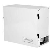
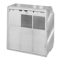
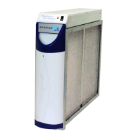
F90A,B SELF-CONTAINED COMMERCIAL ELECTRONIC AIR CLEANER
68-0103-6 Revised 11-07
9
Fig. 7. F90 installation dimensions in in. (mm).
M920
29-1/4
(743)
8
(203)
24
(610)
LATCHES
POWER
CORD
1
ALLOW AT LEAST 9 INCHES (229 MILLIMETERS) FROM
BACK OF F90 TO WALL FOR REMOVAL OF COVER.
7 (178)
1
2
2
ALLOW AT LEAST 16 INCHES (406 MILLIMETERS) FROM
WOOD JOISTS,
16 INCH CENTERS
5-1/2 (140 mm)
Fig. 8. Mounting the F90 using lag screws in joist
applications.
Mounting the F90 Using Threaded
Steel Rod
1. Arrange two 2 x 4 supports as shown in Fig. 9.
2. Drill four 5/16 inch pilot holes through the supports
using the mounting template to locate holes.
3. Mount the steel rods to the supports.
4. Lift the F90 to the mounting location.
5. Mount the F90 to the steel rods by attaching the nuts
and washers.
 Loading...