FIGURE 1. WIRING DIAGRAM:
3
2
1
3
2
1
+
–
–
+
+–
REMOTE ANNUNCIATOR
CAUTION: DO NOT LOOP WIRE
UNDER TERMINAL 1 OR 2.
BREAK WIRE RUN TO PROVIDE
SUPERVISION OF CONNECTIONS.
UL LISTED COMPATIBLE
CONTROL PANEL
OPTIONAL RETURN LOOP
C0100-01
FIGURE 2. ROTARY ADDRESS SWITCHES:
TENS ONES
9
10
11
1 2
1 3
1 4
1 5
8
7
6
5
4
3
2
1
0
9
8
7
6
5
4
3
2
1
0
C0162-00
TAMPER-RESISTANCE
Models SD355, SD355T and AD355 include a tamper-resistant capability that
prevents its removal from the bracket without the use of a tool. Refer to the
base manual for details on making use of this capability.
TESTING
Before testing, notify the proper authorities that the system is undergoing
maintenance, and will temporarily be out of service. Disable the system to
prevent unwanted alarms.
All sensors must be tested after installation and periodically thereafter. Test-
ing methods must satisfy the Authority Having Jurisdiction (AHJ). Sensors
offer maximum performance when tested and maintained in compliance with
NFPA 72. The sensor can be tested in the following ways:
A. Functional: Magnet Test (P/N M02-04-01 or M02-09-00)
This sensor can be functionally tested with a test magnet. The test mag-
net electronically simulates smoke in the sensing chamber, testing the
sensor electronics and connections to the control panel.
1. Hold the test magnet in the magnet test area as shown.
2. The sensor should alarm the panel.
Two LEDs on the sensor are controlled by the panel to indicate sensor
status. Coded signals, transmitted from the panel, can cause the LEDs
to blink, latch on, or latch off. Refer to the control panel technical docu-
mentation for sensor LED operation and expected delay to alarm.
FL-400-002 1 I56-3660-002R
This sensor must be installed in compliance with the control panel system
installation manual. The installation must meet the requirements of the Au-
thority Having Jurisdiction (AHJ). Sensors offer maximum performance when
installed in compliance with the National Fire Protection Association (NFPA);
see NFPA 72.
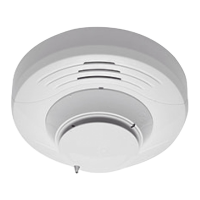
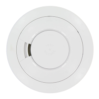
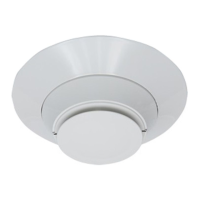
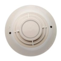
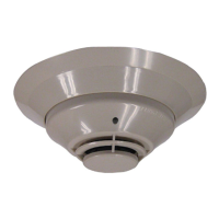
GENERAL DESCRIPTION
Model SD355, SD355T and AD355 are addressable sensors that combine a
state-of-the-art photoelectronic sensing chamber with communications. The
sensors transmit an analog representation of smoke density over a communi-
cation line to a control panel. Rotary decade switches are provided for setting
the sensor’s address.
Two LEDs on the sensor are controlled by the panel to indicate sensor status.
An output is provided for connection to an optional remote LED annunciator
(P/N RA400Z). Models AD355 and SD355T combine a photoelectronic sens-
ing chamber and 135°F (57.2°C) fixed temperature heat detector.
SPACING
Fire-Lite recommends spacing sensors in compliance with NFPA 72. In low
air flow applications with smooth ceilings, space sensors 30 feet apart. For
specific information regarding sensor spacing, placement, and special appli-
cations, refer to NFPA 72 or the System Smoke Detector Application Guide
available from Fire-Lite.
WIRING INSTRUCTIONS
All wiring must be installed in compliance with the National Electrical Code,
applicable local codes, and any special requirements of the Authority Having
Jurisdiction. Proper wire gauges should be used. The installation wires should
be color-coded to limit wiring mistakes and ease system troubleshooting. Im-
proper connections will prevent a system from responding properly in the
event of a fire.
Remove power from the communication line before installing sensors.
1. Wire the sensor base (supplied separately) per the wiring diagram, see
Figure 1.
2. Set the desired address on the sensor address switches, see Figure 2.
3. Install the sensor into the sensor base. Push the sensor into the base
while turning it clockwise to secure it in place.
4. After all sensors have been installed, apply power to the control unit and
activate the communication line.
5. Test the sensor(s) as described in the TESTING section of this manual.
Dust covers provide limited protection against airborne dust particles during
shipping. Dust covers must be removed before the sensors can sense smoke.
Remove sensors prior to heavy remodeling or construction.
I56-3660-002R
INSTALLATION AND MAINTENANCE INSTRUCTIONS
SD355, SD355T and AD355
Addressable Photoelectric Smoke Sensors
SPECIFICATIONS
Operating Voltage Range: 15 to 32 VDC
Standby Current: 300µA @ 24 VDC (one communication every 5 seconds with LED blink enabled)
Maximum Alarm Current (LED on): 6.5 mA @ 24 VDC
Operating Humidity Range: 10% to 93% Relative Humidity, Non-condensing
Operating Temperature Range: 32°F to 120°F (0°C to 49°C); SD355
Operating Temperature Range: 32°F to 100°F (0°C to 38°C); SD355T and AD355
Height: 2.0˝ (51 mm) installed in B350LP Base
Diameter: 6.2˝ (155 mm) installed in B350LP Base
Weight: 5.2 oz. (147 g)
One FireLite Place
Northford, CT 06472
Phone: 203.484.7161