Appendix G: Peripherals Galaxy Flex Installer Manual
238
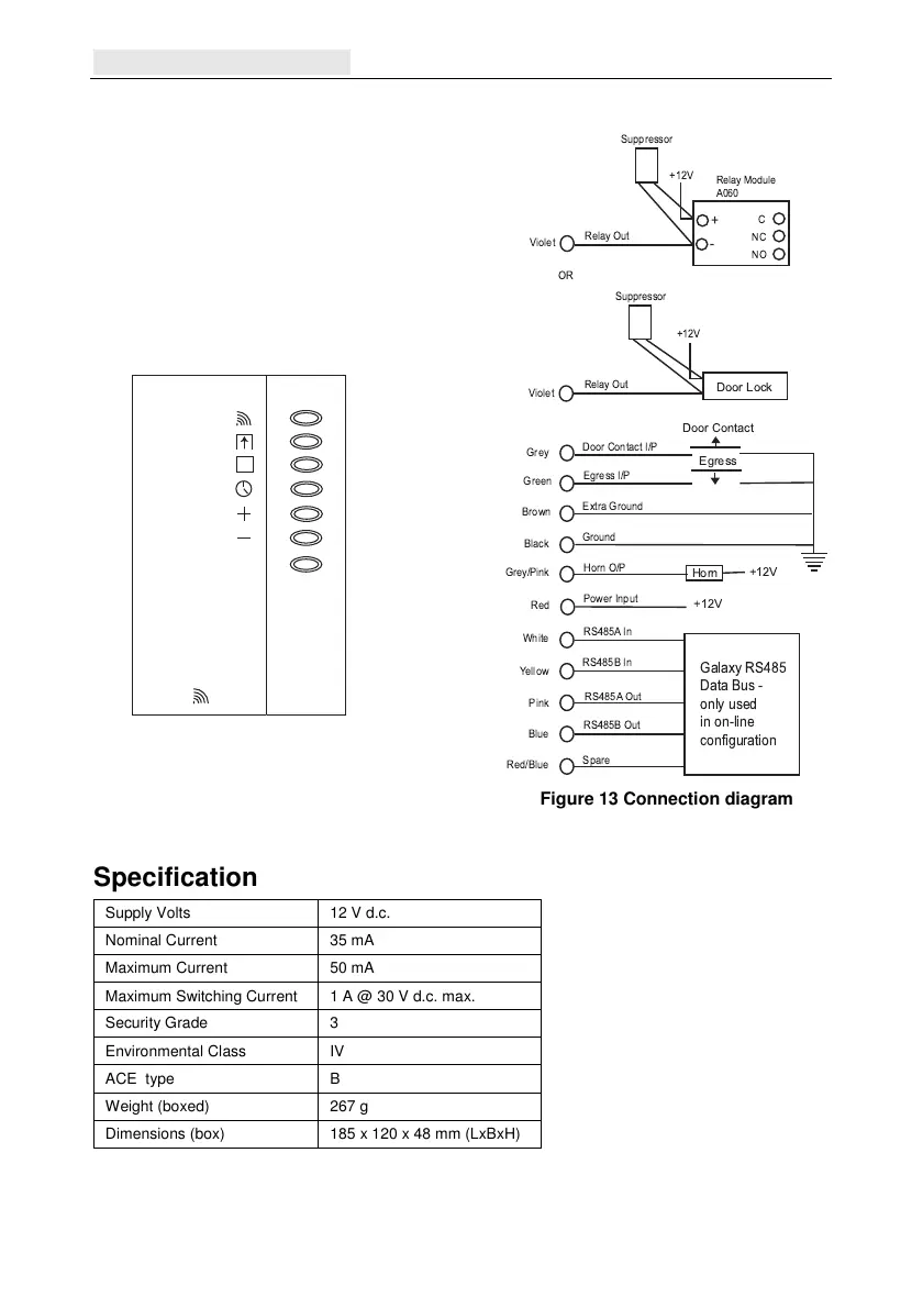
Wiring the MAX
4
The MAX
unit can be connected to the control
panel in online or standalone configuration. The
diagram opposite provides details for both
configurations.
The MAX
4
relay is configured in either the NC
or NO configuration depending upon the variant
purchased (MX04-NC, MX04-NO).
Note: An external relay may be required when
using a.c. powered locks.
x
P
MAX
3
1 = Read (Amber)
2 = Open (Green)
3 = Closed (Red)
4 = Nightlock (Red)
5 = Add (Red)
6 = Void (Red)
7 = Program (Red)
Figure 12 MAX
4
LEDs
Violet
-
+
C
NC
NO
Relay Module
A060
Relay Out
+12V
Suppressor
OR
Violet
Relay Out
Door Lock
Horn
Door Contact I/P
RS485A In
Extra Ground
Power Input
Ground
White
Grey/Pink
Green
Blue
Pink
Yellow
Brown
Grey
Red/Blue
Black
Red
Spare
Horn O/P
Egress I/P
RS485B Out
RS485A Out
RS485B In
Door Contact
Egress
+12V
+12V
Galaxy RS485
Data Bus -
only used
in on-line
configuration
+12V
Suppressor
Figure 13 Connection diagram
Specification
Supply Volts 12 V d.c.
Nominal Current 35 mA
Maximum Current 50 mA
Maximum Switching Current 1 A @ 30 V d.c. max.
Security Grade 3
Environmental Class IV
ACE type B
Weight (boxed) 267 g
Dimensions (box) 185 x 120 x 48 mm (LxBxH)
 Loading...