EasyManua.ls Logo

Honeywell Gent Vigilon A3 Mimic User Manual

Honeywell Gent Vigilon A3 Mimic
4 pages
To Next Page IconTo Next Page
Page #1 background imageLoading...
Page #1 background image
Customised Mimic
Zonal Mimic
A Vigilon A3 Mimic panel (VIG-MIM-A3) must be
connected to a loop circuit of a Vigilon fire detection and
alarm system. It is used to provide indication of fire
events in the system. However it can also be used to
provide indication of fault and supervisory events in the
system. The panel can be mounted in landscape or
portrait orientation.
A Customised Mimic holds a pictorial overlay that
represents the protected building or an area within. A fire
event is indicated by the illumination of appropriate red
LEDs behind the overlay to show the location of the fire.
A Zonal Mimic provides a traditional zone by zone
indication of a fire. Each zone is given a location label to
identify the area within a building.
The panel illumination defaults to a Zonal Mimic but can
be reprogrammed during commissioning to be a
Customised Mimic. An array of red lights illuminates
individually or in groups. Illuminations may be applied to
include custom shapes, text and digital clock in small or
large size. A site specific 'welcome message' may be
configured for display during quiescent conditions that
can scroll if it is too long to fit the display area. First or
last fire flashing option, with in phase or anti phase flash.
The panel has its own mains derived power supply with
battery for standby power in the event of mains supply
failure.
Technical Data
Panel dimensions height 403mm, width 338mm,
depth 101mm
Weight 7.9Kg without batteries
10.5Kg with batteries
Storage temperature -10 to 55ºC
Operating temperature 0 to 45ºC
Relative humidity
(Non condensing)
Up to 90% temperature
5-45°C
Battery 2 x 6V 7Ah sealed lead acid
(weight 1.3Kg each)
The integral battery provides
power for 72 hours in standby
condition and a further
30 minutes in alarm.
Mains operating
voltage
230V 50Hz +10% -6%
Emission BS EN61000-6-3 : 2001
Immunity BS EN50130-4 : 1996 : Part 4
LVD BS EN 60950-2006
Ingress protection IP30 (estimated)
Colour
Door - Pantone 422
Back box - Graphite Grey
(RAL 7024)
Control Cancel fault buzzer / lamp test
button
Indicators 1536 high intensity RED LEDs.
Loop connection 3-way connection to a loop
circuit
Maximum number per
loop
(A maximum load
factor of 1000 allowed
per Vigilon loop circuit)
Maximum number of combined
repeat and mimic panels per
loop = 4
load factor per panel = 3
Typical Mimic illuminations
4188-945_issue 2_05/10_pt1_A3 Mimic 1
Data and Installation
Vigilon A3 Mimic panel
VIG-MIM-A3
by Honeywell
Flashing in phase
or anti phase
Customised Mimic Zonal Mimic
ZONE n
Zone in fire
- steady indication
Latest zone in fire
- flashing indication
Question and Answer IconNeed help?

Do you have a question about the Honeywell Gent Vigilon A3 Mimic and is the answer not in the manual?

Honeywell Gent Vigilon A3 Mimic Specifications

General IconGeneral
Touch TechnologyResistive
Power Supply24 VDC
Display TypeLCD
Operating Temperature0°C to +50°C
Relative Humidity10% to 90% non-condensing
Storage Temperature-20°C to +70°C
Humidity Range10% to 90% non-condensing
Communication InterfaceRS-485

Summary

Vigilon A3 Mimic Panel Overview

Customised Mimic Panel

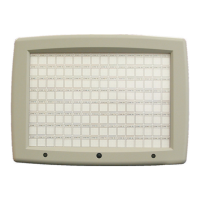
Pictorial overlay representing protected building or area. Fire event indicated by red LEDs.

Zonal Mimic Panel

Traditional zone-by-zone indication of fire. Each zone has a location label.

Typical Mimic Illuminations

Examples of how Customised and Zonal Mimics display fire events using LEDs.

Compatibility and Installation

Compatibility Requirements

System control panel software requirements for Zonal and Customised Mimic panels.

Mounting the Backbox

Instructions for mounting the Mimic panel backbox in landscape or portrait orientation.

Installation Components

List of components included in the Mimic Panel set for installation.

Wiring and Assembly Procedures

External Wiring Connections

Routing external cables into the back box for loop and mains connections.

Internal Cable Connections

Connecting internal cables from the back box to the inner door and Master Repeat Card.

Fitting the Inner Door Assembly

Step-by-step guide on how to attach the inner door assembly to the backbox.

Flat Flexible Cable Handling

Procedures for connecting and disconnecting flat flexible cables to the Master Repeat Card.

Setting the SW3 Switch

Instructions for setting the SW3 switch on the Master Repeat Card for Mimic panel operation.

Final Setup and Overlays

Power Up and Battery Operation

Connecting battery, mains power, and powering up the panel.

Lamp Test Functionality

How to perform a lamp test to check LEDs and the internal buzzer.

Overlay Application

Instructions for applying Zonal and Customised Mimic overlays to the panel.

Fitting the Outer Cover

Steps to attach and secure the outer cover to the Mimic panel.

Related product manuals