Do you have a question about the Honeywell KI 209 and is the answer not in the manual?
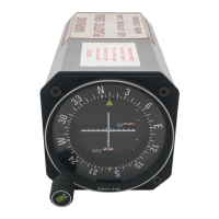
Details functions and features of the KI 208 VOR and KI 209 ILS indicators.
Lists specifications and characteristics for KI 208 and KI 209 indicators.
Lists included units and accessories for KI 208 and KI 209.
Specifies requirements for a TSO-compliant navigation system using the KI 208/209.
Covers the step-by-step process for installing the KI 208 and KI 209 indicators.
Outlines recommended operational tests after installing the KI 208/209.
Diagram showing pin connections for the KI 208 navigation indicator.
Diagram showing pin connections for the KI 209 navigation indicator.
Provides dimensional drawings and mounting information for KI 208 and KI 209.
Illustrates wiring interconnects for KI 208/209 with aircraft systems.
Details how to operate the KI 208/209 indicators, covering VOR, Localizer, and Glideslope functions.
Explains the function of controls like OBS, VOR/LOC deviation, and Glideslope deviation indicators.
| Brand | Honeywell |
|---|---|
| Model | KI 209 |
| Category | Touch Panel |
| Language | English |