INSTALLATION INSTRUCTIONS
H7625B, H7626B, H7635B,C
H7636B, H7655B, H7656B
DUCT-MOUNT AND OUTDOOR-MOUNT HUMIDITY/
TEMPERATURE SENSORS
APPLICATION
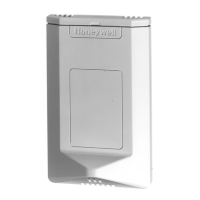
The H76XXB Duct-Mount and H76XXC Outdoor-Mount
Humidity/Temperature Sensors are universal Relative
Humidity transmitters that can be powered with either a
+18 to 40 Vdc or 24 Vac supply . The devices are half
wave rectified. The transmitter also includes either a 20K
ohm NTC thermistor or a 1K platinum PTC (compatible
with the T775) for optional temperature use.
The humidity sensors are designed with a field selectable
4 to 20 mA, 0 to 5 Vdc, or 0 to 10 Vdc output signal
equivalent to 0 to 100% RH. All units are shipped from
the factory with a default setting to accept AC power with
three-wire, 0 to 10 Vdc output.
INSTALLATION
When Installing this Product...
1. Read these instructions carefully. Failure to follow
them could damage the product or cause a
hazardous condition.
2. Check ratings given in instructions and on the
product to ensure the product is suitable for your
application.
3. Installer must be a trained, experienced service
technician.
4. After installation is complete, check out product
operation as provided in these instructions.
Electrical Shock or Equipment Damage
Hazard.
Can shock individuals or short equipment
circuitry.
Disconnect power supply before installation.
Equipment Damage Hazard.
Improper wiring can damage the sensor
beyond repair.
Follow the wiring instructions carefully.
Mounting
The method of mounting depends on the particular
sensor application. The following procedures include
outdoor and duct applications. Also refer to the
instructions for the electronic control.
Duct mounting Configuration
The H7625B, H7626B, H7635B, H7636B, H7655B and
H7656B can be mounted in a duct to sense humidity and
temperature.
IMPORTANT
Select a location to expose sensor to average
duct humidity and temperature. Avoid locations
where stratification can cause sensing errors.
NOTES:
• Knockouts allow 1/2 in. conduit connection. To avoid
damaging board during installation, the cover can be
detached completely:
• Carefully remove wire plug from board.
• Set the cover aside.
1. Drill a 3/4” diameter hole in the duct where the
transmitter is to be mounted.
2. Insert the stainless steel probe into the hole until
the foam is in direct contact with the duct.
3. Attach the transmitter to the duct using the sup-
plied #8 X 3/4” self-tapping screws.
4. Remove the cover and install your conduit connec-
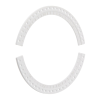
tor or watertight fitting. The outer ring is used when
using a 1/2” NPT conduit fitting.
5. After wiring the unit, place the cover back on and
gently turn it until it is tight.
Outdoor Mounting Configuration
The H7635C senses outdoor air humidity and
temperature. Mount this control where it can sense
average outdoor air humidity and temperature. Normally,
the north side of a building provides a suitable location.
NOTES:
• H7635C is weatherproof for outdoor use. Knockouts
allow 1/2 in. conduit connection.
• To avoid damaging board during installation, the cover
can be detached completely:
• Carefully remove wire plug from board.
• Set the cover aside.