OSD Controller
To access the OSD menu, press
the controller joystick. Then move
the joystick up/down/left/right to
navigate through the setup options.
Monitor Out (2nd Video)
To verify that the view angle and
camera settings are correct, you
can connect to a portable monitor
using the supplied adapter cable.
Note For detailed information regarding OSD menu options, refer to your model’s
user guide.
Legend
A =
Power connector
B =
BNC connector
C =
UTP connector
Do not touch or damage
the black vent.
Preparation Installation Setup
3. Connect the Wiring
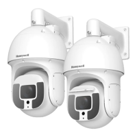
Surface Mount
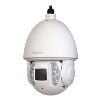
1. Disassemble the Camera
2. Prepare the Mounting Surface (Surface or Flush Mount)
a. Using the supplied 5/32-inch Allen key,
loosen the three captive screws
attaching the dome cover to the base
and carefully remove the dome cover.
b. Gently pull the inner liner off of the base.
c. Loosen the three M4×10 captive screws
connecting the base to the skirt, and
then lift the base off of the skirt.
4S Electrical Junction Box (Optional)
a. Attach the adapter plate to the electrical
box using suitable screws (not supplied).
b. Attach the base to the adapter plate using
the supplied M4×10 captive screws.
Electrical box
(not supplied)
Base
Flush Mount
•
With adapter plate:
Attach the base to the
mounting surface and plate using the supplied
M4×45 screws. (You will need to remove the
M4×10 captive screws first)
•
Without adapter plate:
Attach the base to the
mounting surface using suitable screws (not
supplied).
Skirt
To reattach the dome cover after you
have mounted the camera and adjusted
the settings (
2, 3
):
a. Push the inner liner onto
the base until it snaps into place.
b. Push the dome cover onto the base
and tighten the security screws.
Base
Base
Screws
(not supplied)
M4×45 screws
(supplied)
M4×10 screws
(supplied)
Screws
(not supplied)
M4×10 screws
(supplied)
Inner liner
Dome cover
a. Using the appropriate
mounting template, mark
the holes as required.
b. Insert screw anchors (not
supplied) into the holes.
Base
Skirt
Flush Mount
Surface Mount
a. Attach the skirt to the electrical box
using suitable screws (not supplied).
b. Attach the base to the skirt using the
supplied M4×10 captive screws.
M4×10 screws
(supplied)
Screws
(not supplied)
Skirt
Base
a. Attach the skirt to the mounting surface
using suitable screws (not supplied).
b. Attach the base to the skirt using the
supplied M4×10 captive screws.
1
2
3
Note Surface mount preparation shown.
Adapter plate
(optional)
Adapter plate
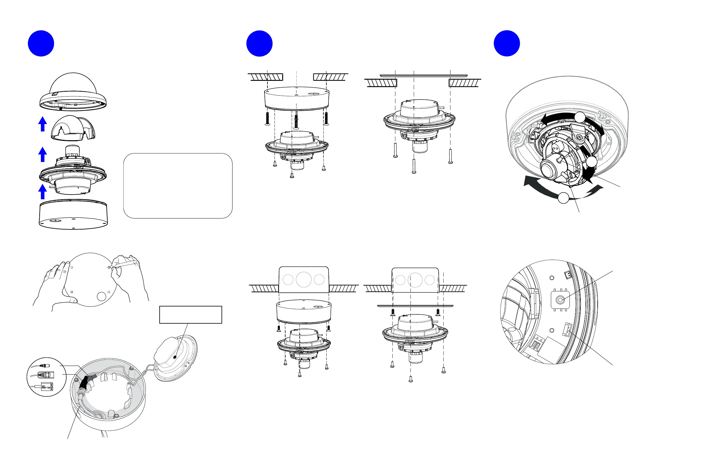
Focus lever**
(top)
2. Configure the Camera Settings Using the OSD
1. Adjust the View Angle
A
C
B
A
B
C
a. Connect the video connector:
• BNC: Connect to a mating BNC
connector.
• UTP: Connect the blue wire to
Video+. Connect the white wire
to Video−.
b. Connect the 24 V AC/12 V DC
power connector.
c. Route wiring behind posts
(grayed area).
Electrical box
(not supplied)
To use the side conduit, remove the security
screw with the supplied 1.5 mm Allen key, and
then unscrew the conduit plug.
**Not applicable to HD4DAFS(X)

 Loading...