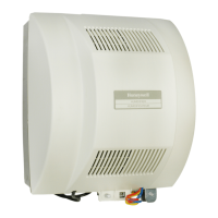
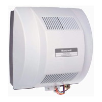
HE440A, HE480A STEAM POWER HUMIDIFIER
5 68-0265EF-1
Fig. 5. Mounting hole location.
Mount Horizontally on Reinforced Duct
This method usually requires duct reinforcement to support
the weight of the humidifier and keep it level. See Fig. 3. The
mounting bracket is not used.
1. Measure and mark an 8-1/2 in. (215 mm) x 11-1/2 in.
(290 mm) outline on the bottom of the duct in the
desired location.
2. Drill 3/8 in. hole (10 mm) within the outlined mounting
hole location.
IMPORTANT
Be sure to carefully cut around the marked lines.
3. Use the tin snips to cut around the outline.
4. Remove the sheet metal.
5. Place the two 8-1/2 in. (215 mm) S-cleat pieces on the
narrow sides of the rectangular opening so the opening
(slot) protrudes down and out of the duct.
6. Place the 11-1/2 in. (290 mm) piece of S-cleat on the
long side of the rectangular opening, opposite the two
holes previously drilled. Position so the opening (slot)
protrudes down and out of the duct.
7. Slide the humidifier tabs into the installed S-cleat. Be
sure the back tab engages completely with the S-cleat.
8. Secure the humidifier to the duct with two no. 8 sheet
metal screws (not provided).
Mount Horizontally on Vertical Duct
Horizontal mounting on a vertical duct requires the installation
of a duct extension. See Fig. 4. Additional duct reinforcement
may also be necessary to help support the weight of the
humidifier and keep it level.
Create and install the duct extension. Then follow steps 1
through 10 in Mount Horizontally Using Mounting Bracket
section to complete installation.
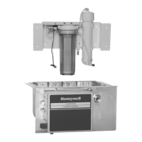
Mount Two-Stage Water Treatment System Bracket
to Wall
NOTE: Be sure bracket is level.
Use four screws (not provided) to secure mounting bracket to
exposed wall studs or flat wall through mounting holes
provided. See Fig. 6.
Fig. 6. Mounting water system on wall.
NOTE:
— Be sure there is an accessible drain near the
water treatment system.
— Plan system location considering 20 ft (6m) cable
(provided) to connect water treatment system to
humidifier.
— Be sure there is adequate clearance above and
below the system to replace the filters. See
Fig.12.
WIRING
All wiring must comply with local codes and ordinances. When
selecting a location for mounting the humidifier, be sure
connections can be made to the power source without using
an extension cord.
WARNING
Voltage or Fire Hazard.
Can cause death or fire.
Use a receptacle rated at 120 Vac, 15/20A (NEMA
configuration 5-15R) for the HE440A Humidifier.
Use a receptacle rated at 240 Vac (NEMA
configuration 6-15R) for the HE480A Humidifier.
M20329
3/4 IN. (19 MM)
FROM EDGE
M2033
BRACKET AND HOLES (4)
FOR MOUNTING ON STUDS
HOLES (4) FOR FLAT
WALL MOUNTING
 Loading...