HPFF12 NAC Expander — P/N 53576:B 11/24/2010 47
Connecting Multiple Units Applications
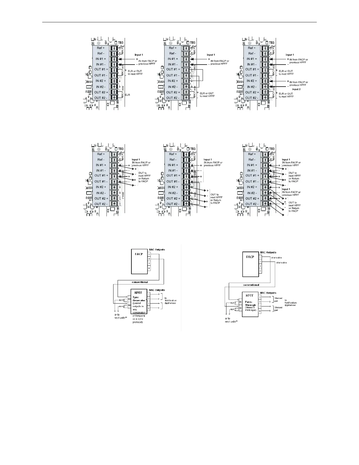
Figure 5.7 Class B Input Connections
w
Figure 5.8 Class A Input Connections
NOTES for Figures 5.5–5.10:
1. The FACP’s NAC output must be regulated (not Full Wave Rectified [FWR]) if the HPFF is programmed for
Sync Generator.
2. The number of possible units that can be interconnected depends on the current capability of the FACP
output. Each HPFF8 input draws 12.26 mA at 24 VDC.
3. The total line impedance for interconnected units cannot be such that it creates a voltage drop > 2 VDC.
Zline total =2V/(1 Unit + 1 ELR)
Example: Zline total = 2V/(12.26 mA + (24-2)/4.7K) =118.1 ohms
Figure 5.9 Split Alarm Connections Figure 5.10 Selective Silencing
Connections
 Loading...


