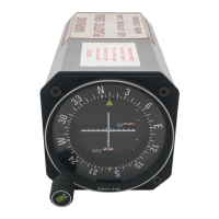
BENDIX/KING KI 208, KI 209
Rev 4, Aug 2002 IM 006-00140-0004 Page 1-4
1.7.1.4 Variation in the LOC composite output shall not exceed ±2 dB from 0.333
Vrms as the RF input level of a Standard Localizer Centering Signal is varied
from 50 uV to 10,000 uV.
1.7.1.5 A control line (ILS Energize) must be provided as a low impedance to ground
when an ILS frequency is selected.
1.7.2 Glideslope Receiver/Converter Requirements For Use with KI 209.
1.7.2.1 The glideslope receiver/converter shall be authorized to the standards of TSO
C34c, C34d, C34e.
1.7.2.2 Centering current to be 0 ±7 uA into a 1000 ohm load with a 95% probability
under all combinations of the service conditions listed in RTCA Paper DO-132,
Minimum Performance Standards - Airborne ILS Glideslope Receiving Equip-
ment paragraph 2.1 sub-paragraph b, Centering Accuracy.
1.7.2.3 Deviation current with a 700 uV Standard Glideslope Deviation Signal (0.091
±0.001 ddm tone ratio) applied to the receiver input shall be 78 ±10% uA into
a 1000 ohm load. Deviation current shall not change more than 15% as the
RF input level of a Standard Glideslope Deviation Signal is varied from 100 to
10,000 uV. Deviation current shall be proportional within 5% to the difference
in depth of modulation of the 90 Hz and 150 Hz tones.
1.7.2.4 Warning signal output shall be a DC current less than 125 uA into a 1000 ohm
load for a warning flag to be fully visible. Warning signal for a fully concealed
warning flag shall be a DC current of 260 uA minimum into a 1000 ohm load.
1.7.3 Fully TSO’D Systems
The following navigation systems will meet all TSO system requirements when
used in conjunction with the KI 208, KI 209:
KX 155
KX 155A
KX 165A
RELEASED FOR THE EXCLUSIVE USE BY: AIRCRAFT ELECTRONICS ASSOCIATION
UP536434

 Loading...