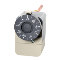
CYLINDER THERMOSTATS L641A/L6190B
■ Installation
T
he L6190 and L641 can be
installed horizontally or vertically.
The Cylinder Thermostats can be fixed
t
o the surface of a cylinder or
pipework using the mounting straps
provided and does not require the
system to be drained.
If located on a cylinder, the
recommended position is
1
/
3
up from
the bottom of the cylinder. Any foam
lagging should be removed to allow
firm contact with the cylinder.
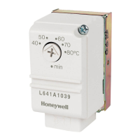
■ Ordering Specification
L641A1039
Cylinder Thermostat, setting 40 to
80˚C, Diff. 10°C. With strap & optional
dial
L6190B1014
Cylinder Thermostat, setting 25 to
95˚C, Diff. 12°C with strap
■ Specification
L641B
Switch Rating : 230VAC, 4A resistive, 2A inductive
S
witch Type : Single pole, double throw (SPDT)
Ambient Temperature Range : 0 to 55˚C
Surface Temperature Range : 0 to 95˚C
IP Rating : IP40
Standards : EN 60730
Approvals : 89/336/EEC, 73/23/EEC
L6190B
Switch Rating : 250VAC, 10A resistive, 2.5A inductive
Switch Type : Single pole, double throw (SPDT)
Ambient Temperature Range : 0 to 70˚C
Surface Temperature Range : 0 to 95˚C
IP Rating : IP40
Standards : CE, UL, AGA, CSA
Approvals : 73/23/EEC, DIN3440
■ Dimensions (mm)
■ Wiring
 Loading...