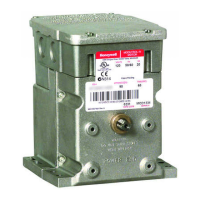
SERIES 71, 72, AND 76 MODUTROL IV™ MOTORS
63-2640—07 10
Fig. 11. Sequential operation of motors.
Enhanced Resolution
M7284C1083, M7284C1091, M7284Q1082,
and M7284Q1090
These four motors have enhanced resolution with 160
repositions (steps) from 90 degrees to 160 degrees stroke.
Auxiliary Switches
Electrical Shock or Equipment Damage Hazard.
Can shock individuals or short equipment
circuitry.
Disconnect all power supplies before installation.
Motors with auxiliary switches can have more than one
disconnect.
Equipment Damage Hazard.
Can damage the motor beyond repair.
Never turn the motor shaft by hand or with a wrench.
Forcibly turning the motor shaft damages the gear train
and stroke limit contacts.
Adjustable cams actuate the auxiliary switches. These cams
can be set to actuate the switches at any angle within the
motor stroke. Select switch differential of 1° or 10°.
Motors with factory added auxiliary switches are shipped in the
closed position (fully counterclockwise, as viewed from the
motor power end) with auxiliary cams set to actuate switches
30° from the closed position and to provide 1° degree
differential. With the motor in the closed (fully counter-
clockwise) position, the auxiliary switch breaks contacts R-B.
See Fig. 12 for auxiliary switch wiring.
Series 2 Motors are shipped with auxiliary switch cams that
permit acceptance of 220736A,B Internal Auxiliary Switch Kits.
Refer to form 63-2228 for 220736A,B Installation Instructions.
Auxiliary Switch Adjustment
IMPORTANT
When adjusting the auxiliary switch cams use the
following procedure:
1. Insert 1/8 in. screwdriver blade into a slot on cam and
move the screwdriver top as far as possible in the
required direction. See Fig. 12.
2. Repeat step 1 in successive cam slots until the cam is
in the required position.
NOTE: Series 2 Motors are shipped with auxiliary switch
cams that permit acceptance of 220736A,B Internal
Auxiliary Switch Kits. Refer to Form no. 63-2228 for
220736A,B Installation Instructions.
Use the following procedure to obtain the desired auxiliary
switch settings:
1. Remove the top cover from the motor to gain access
to the motor terminals and auxiliary cams.
2. Disconnect the controller from the motor.
3. Connect a current source to the positive and negative
terminals.
4. Drive the motor to the position where the auxiliary equip-
ment is to be switched by increasing or decreasing the
current.
5. For a switch differential of 1°, check continuity of auxiliary
switch contacts R-B and rotate the cam as follows:
a. If the contacts are open, rotate the cam clockwise
until the R-B contacts close.
b. If the contacts are closed, rotate the cam
counterclockwise until the R-B contacts open.
6. For a switch differential of 10° rotate the cam
approximately 180° so the slow-rise portion of the
cam actuates the switch.
7. Check continuity of the auxiliary switch contacts R-B.
8. Rotate the cam as follows:
a. If the contacts are open, rotate the cam
counterclockwise until the R-B contacts close.
b. If the contacts are closed, rotate the cam clockwise
until the R-B contacts open.
c. Make final adjustment in the proper direction to
obtain contact make or break at the desired position.
9. Check for the proper differential and switching of the
auxiliary equipment by driving the motor though the full
stroke in both directions.
10. Disconnect power, remove current source, reconnect the
controller, and replace the top cover on the motor.
NOTE: Changing the differential from 1° to 10° reverses the
switching action. For example, with a 10° differential,
switch contacts R-B make and R-W break on a
counterclockwise (closed) rotation. With a 1°
differential, switch contacts R-W make and R-B break
on a counterclockwise (closed) rotation.
20
(10)
16
(8)
12
(6)
8
(4)
4
(2)
0
CONTROL OUTPUT
mA CURRENT (OR VOLTS DC)
CLOSED
OPEN
CLOSED
OPEN
CLOSED OPEN
MOTOR 1 MOTOR 2 MOTOR 3
1 3 3 3
1
MOTOR 1 PROPORTIONS BETWEEN 4 AND 12 mA; FULLY
CLOSED AT 4 mA, FULLY OPENED AT 12 mA.
MOTOR 2 PROPORTIONS BETWEEN 8 AND 16 mA; FULLY
CLOSED AT 8 mA, FULLY OPENED AT 16 mA.
MOTOR 3 PROPORTIONS BETWEEN 12 AND 20 mA SIGNAL;
FULLY CLOSED AT 12 mA, FULLY OPENED AT 20 mA.
UP TO 6 MOTORS CAN BE DRIVEN SEQUENTIALY OR IN
UNISON FROM ONE CONTROLLER.
ADJUST ZERO ADJUST AND SPAN ADJUST POTENTIOMETERS
TO ACHIEVE DESIRED SEQUENCE.
2
2
3
SEQUENTIAL OPERATION
FOR ADJUSTABLE ZERO AND SPAN MODELS
M2893A
 Loading...
