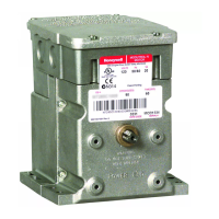
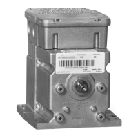
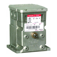
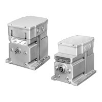
SERIES 72 MODUTROL IV™ MOTORS
63-2202—410
SETTINGS AND ADJUSTMENTS
Zero and Span Adjustment for M7284Q and
M7285Q Motors (Fig. 5.)
1.
Adjust the start potentiometer fully clockwise (maximum
zero) and the span potentiometer fully counterclockwise
(minimum span).
2.
Set the controller current to the value required to drive
the motor to the closed position.
3.
Turn the start potentiometer slowly counterclockwise
until the motor begins to open. This is defined as the
start or zero setting.
4.
Set the controller current to the value required to drive
the motor to the fully open position. The motor will open.
5.
Turn the span potentiometer clockwise until the motor
starts to close. The difference between the fully open
span position current and the zero position current is
defined as the operating span.
6.
Recheck the start and readjust the span potentiometer
P1 if necessary. Turn the start potentiometer clockwise
to increase the zero position.
7.
Recheck the span and readjust the span potentiometer
if necessary. Turn it clockwise to increase the full span
position.
8.
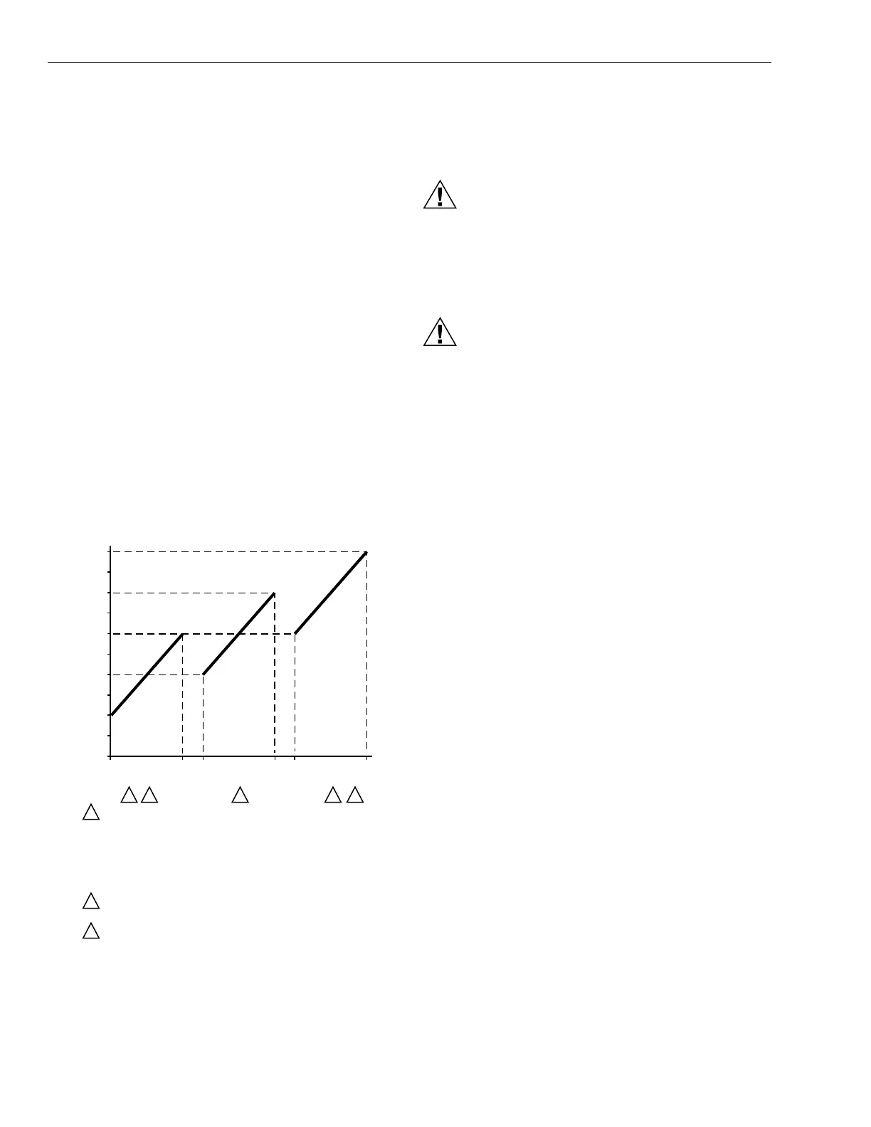
For sequential operation, as shown in Fig. 9, repeat the
above steps for each motor.
Fig. 9. Sequential operation of motors.
Auxiliary Switches
CAUTION
Electrical Shock or Equipment Damage Hazard.
Can shock individuals or short equipment
circuitry.
Disconnect all power supplies before installation.
Motors with auxiliary switches can have more than
one disconnect.
CAUTION
Equipment Damage Hazard.
Can damage the motor beyond repair.
Never turn the motor shaft by hand or with a wrench.
Forcibly turning the motor shaft damages the gear
train and stroke limit contacts.
Adjustable cams actuate the auxiliary switches. These cams
can be set to actuate the switches at any angle within the
motor stroke. Select switch differential of 1° or 10°.
Motors with factory added auxiliary switches are shipped in
the closed position (fully counterclockwise, as viewed from the
motor power end) with auxiliary cams set to actuate switches
30° from the closed position and to provide 1° degree
differential. With the motor in the closed (fully
counterclockwise) position, the auxiliary switch breaks
contacts R-B. See Fig. 10 for auxiliary switch wiring.
TRADELINE Motors are shipped with auxiliary switch cams
that permit acceptance of 220736A,B Internal Auxiliary Switch
Kits. Refer to form 63-2228 for 220736A,B Installation
Instructions.
20
(10)
16
(8)
12
(6)
8
(4)
4
(2)
0
CONTROL OUTPUT
mA CURRENT (OR VOLTS DC)
CLOSED
OPEN
CLOSED
OPEN
CLOSED OPEN
MOTOR 1 MOTOR 2 MOTOR 3
1 3 3 3
1
MOTOR 1 PROPORTIONS BETWEEN 4 AND 12 mA; FULLY
CLOSED AT 4 mA, FULLY OPENED AT 12 mA.
MOTOR 2 PROPORTIONS BETWEEN 8 AND 16 mA; FULLY
CLOSED AT 8 mA, FULLY OPENED AT 16 mA.
MOTOR 3 PROPORTIONS BETWEEN 12 AND 20 mA SIGNAL;
FULLY CLOSED AT 12 mA, FULLY OPENED AT 20 mA.
UP TO 6 MOTORS CAN BE DRIVEN SEQUENTIALY OR IN
UNISON FROM ONE CONTROLLER.
ADJUST ZERO ADJUST AND SPAN ADJUST POTENTIOMETERS
TO ACHIEVE DESIRED SEQUENCE.
2
2
3
SEQUENTIAL OPERATION
FOR ADJUSTABLE ZERO AND SPAN MODELS
M2893A
 Loading...