SERIES 72 MODUTROL IV™ MOTORS
11 63-2202—4
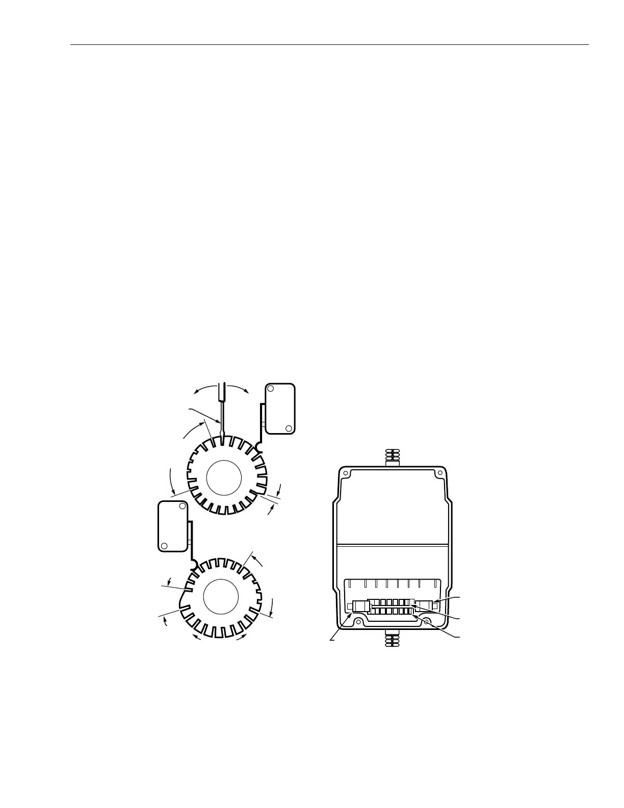
Auxiliary Switch Adjustment
IMPORTANT
When adjusting the auxiliary switch cams use the
following procedure:
1.Insert 1/8 in. screwdriver blade into a slot on cam
and move the screwdriver top as far as possible in
the required direction. See Fig. 10.
2.Repeat step 1 in successive cam slots until the
cam is in the required position.
Use the following procedure to obtain the desired auxiliary
switch settings:
1.
Remove the top cover from the motor to gain access
to the motor terminals and auxiliary cams.
2.
Disconnect the controller from the motor.
3.
Connect a current source to the positive and negative
terminals.
4.
Drive the motor to the position where the auxiliary
equipment is to be switched by increasing or decreasing
the current.
5.
For a switch differential of 1°, check continuity of auxiliary
switch contacts R-B and rotate the cam as follows:
a. If the contacts are open, rotate the cam clockwise
until the R-B contacts close.
b. If the contacts are closed, rotate the cam
counterclockwise until the R-B contacts open.
6.
For a switch differential of 10° rotate the cam
approximately 180° so the slow-rise portion of the
cam actuates the switch.
7.
Check continuity of the auxiliary switch contacts R-B.
8.
Rotate the cam as follows:
a. If the contacts are open, rotate the cam
counterclockwise until the R-B contacts close.
b. If the contacts are closed, rotate the cam clockwise
until the R-B contacts open.
c. Make final adjustment in the proper direction to
obtain contact make or break at the desired position.
9.
Check for the proper differential and switching of the
auxiliary equipment by driving the motor though the full
stroke in both directions.
10.
Disconnect power, remove current source, reconnect
the controller, and replace the top cover on the motor.
NOTE: Changing the differential from 1° to 10° reverses the
switching action. For example, with a 10° differential,
switch contacts R-B make and R-W break on a
counterclockwise (closed) rotation. With a 1°
differential, switch contacts R-W make and R-B
break on a counterclockwise (closed) rotation.
Fig. 10. Auxiliary switch adjustment.
RIGHT/INNER
AUXILIARY
SWITCH
FAST RISE
PORTION
(APPROX.
1° DIFF.)
SLOW RISE
PORTION
(APPROX.
10° DIFF.)
INNER
AUXILIARY
CAM
(BLUE)
NOTE: CAMS ARE OFFSET
VERTICALLY TO PROVIDE
BETTER VIEW OF BACK CAM.
FAST RISE
PORTION
(APPROX.
1° DIFF.)
SLOW RISE
PORTION
(APPROX.
10° DIFF.)
MOTOR
OPEN
MOTOR
CLOSE
POWER
END
OUTER
AUXILIARY
CAM
(RED)
LEFT/OUTER
AUXILIARY
SWITCH
M17101
POWER END
OF MOTOR
OUTER AUXILIARY
CAM (RED)
INNER AUXILIARY
CAM (BLUE)
RIGHT/INNER
AUXILIARY SWITCH
LEFT/OUTER
AUXILIARY
SWITCH
MOVE SCREWDRIVER AT
TOP ONLY TO ADJUST CAM.
1/8 INCH
STRAIGHT-BLADE
SCREWDRIVER
 Loading...