SERIES 61 AND SERIES 62 MODUTROL IV™ MOTORS
63-2629EF—01 6
— Crank arm rotation through the downward position.
— Sufficient damper linkage to reach the motor shaft.
• All valve linkages except the Q5001.
NOTE: When the bracket is not used in a replacement
application, the damper linkage requires adjust-
ment for the new shaft position.
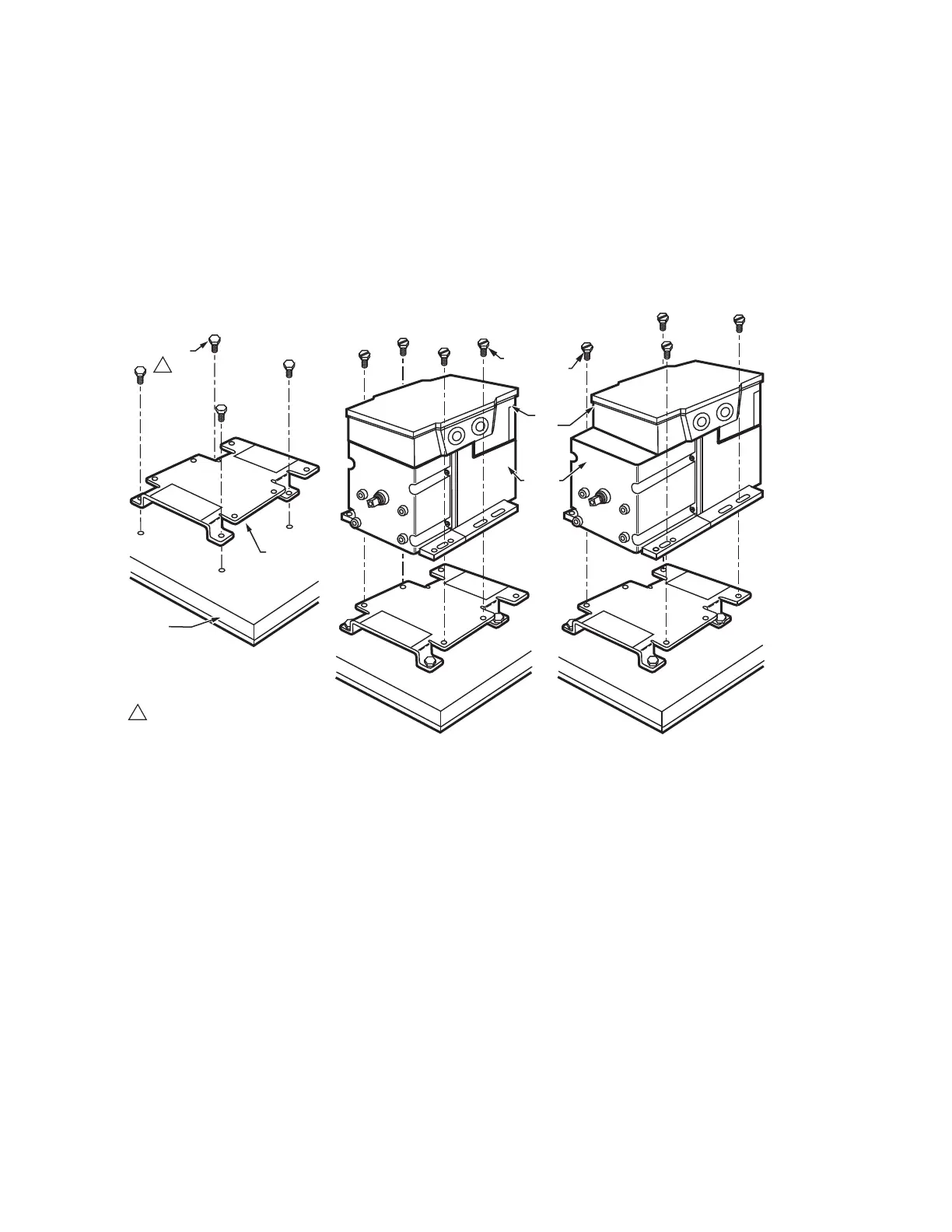
To mount the motor with the bracket:
1. Mount the bracket to the equipment with existing or
standard bolts.
2. Using the provided bolts, mount the motor to the bracket
threaded holes. See Fig. 3.
For valve linkage applications (other than the Q5001):
1. Mount the bracket to the linkage.
2. Position the motor on the bracket to align the motor
shaft with the linkage.
3. Attach the motor to the bracket with the four bolts
provided. See Fig. 4.
Fig. 3. Mounting the motor with an adapter bracket.
M18999
EQUIPMENT
BASE
ADAPTER
BRACKET
STANDARD
BOLTS (4)
MOTOR
BOLTS
PROVIDED (4)
WIRING
BOX
NON-SPRING RETURN
SPRING RETURN
1 #12 OR 1/4" ZINC PLATED
MACHINE SCREWS OR BOLTS
1
PO
W
ER
END
POW
ER
END
POW
ER
END
 Loading...