63-2202—4 B.B. Rev. 11-00 www.honeywell.com
Printed in U.S.A. on recycled
paper containing at least 10%
post-consumer paper fibers.
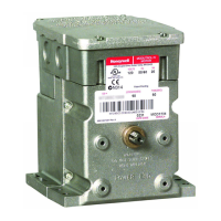
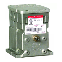
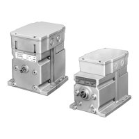
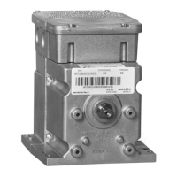
SERIES 72 MODUTROL IV™ MOTORS
Home and Building Control Home and Building Control Honeywell Asia Pacific Inc. Honeywell Europe S.A. Honeywell Latin American
Honeywell Honeywell Limited-Honeywell Limitée Room 3213-3225 3 Avenue du Bourget Region
1985 Douglas Drive North 35 Dynamic Drive Sun Hung Kai Centre 1140 Brussels 480 Sawgrass Corporate Parkway
Golden Valley, MN 55422 Scarborough, Ontario No. 30 Harbour Road Belgium Suite 200
M1V 4Z9 Wanchai Sunrise FL 33325
Hong Kong
OPERATION AND CHECKOUT
Operation
The motor feedback potentiometer and control current input
circuit form a bridge circuit. As long as the final control
element remains at the position proportional to the input
current from the controller, the circuit is balanced, and the
motor does not run. When the value of the controlled medium
changes, the current from the controller changes, and
unbalance is amplified to energize the Triac switching to run
the motor in the proper direction to correct the change in the
temperature or the pressure. The motor turns the feedback
potentiometer to rebalance the circuit and stop the motor.
Checkout
After installation and linkage adjustment, operate the motor
through the controller. Make sure that:
• The motor properly operates the damper or valve.
• The motor responds properly as the input is varied.
• The auxiliary switch, if used, operates at the desired point
of motor rotation.
Inspect the motor, linkage, and valve or damper to see that all
mechanical connections are correct and secure.
In damper installations, the pushrod should not extend more
than a few inches past the ball joints. Check to see that
there is adequate clearance for the linkage to move through
its stroke without binding or striking other objects.
See controller or system instructions for additional checkout
procedures.
Motor Operation Checkout
Check motor operation as follows:
1.
To close the motor, open terminals +, -, and F.
2.
To open the motor, connect terminal F to the
negative (-) motor terminal.
 Loading...