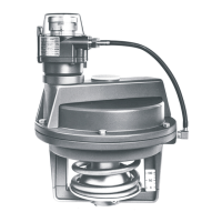
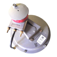
MP909E UL LISTED DAMPER ACTUATOR
95-6076
2
17
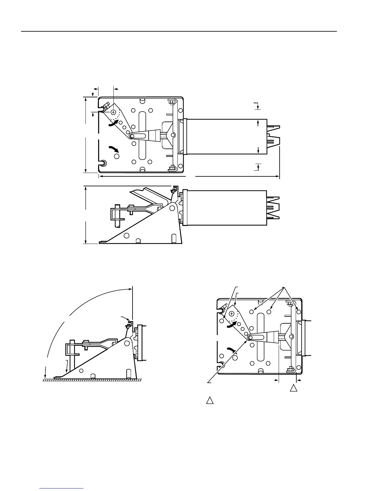
(430)
1-1/8 (30) CLEARANCE
1-1/8 (30) CLEARANCE
MP909E
1-1/2
(39)
1-1/2
(39)
6-7/8
(175)
5-3/4
(145)
AXLE
ROTATION TO
NORMAL
C8092
Fig 1. External Mounting Dimensions in Inches (Millimeters).
FACEPLATE
MOUNTING
BRACKET
C8209
90°
AXLE
ROTATION TO
NORMAL
MOUNTING HOLES
C8208
CRANKARM
CLEVIS PIN LOCATION ON
3.1-INCH STROKE OPERATORS
(FACTORY INSTALLED)
1-3/8(35)
REF.
1-5/8 INCH (41 MM) FOR 3.1 INCH STROKE
OPERATORS AND N.C. DAMPERS
1
1
Fig. 2. External Mounting Faceplate Positioning.
Fig. 3. External Installation.
5 Remove mounting screw from damper end of truss link.
Loosen screw between base and truss link. Remove
clevis pin from damper end of actuator pushrod.
6 Set actuator in place by hooking actuator mounting
clamp over bottom edge of damper frame.
7 Set damper to the normal (closed) position.
8 Insert clevis pin in drive ear hole marked P and the
pushrod hole nearest the actuator.
9 Connect truss link to damper and tighten both truss link
screws.
J Tighten damper mounting screws.
K Go to PIPING section.