EasyManua.ls Logo

Honeywell M7410E - User Manual

Honeywell M7410E
6 pages
To Next Page IconTo Next Page
Loading...
EN0B-0097GE51 R1004
M7410E
SMALL MODULATING LINEAR
VALVE ACTUATOR
PRODUCT DATA
0..10V
2..10V
0%..100%
100%..0%
APPLICATION
The Honeywell M7410E actuator is specifically designed to
provide modulating control together with the V5822/23,
V5832/33, and V5825B series of small linear valves.
The M7410E is used in fan-coil-units, induction units, small
reheaters and recoolers, and for zone control applications. It
is employed in electronic temperature control systems with
hot and/or cold water as the controlled medium. This actuator
is fully compatible with all controllers providing 0...10 V or
2...10 V output signals.
The 7410E actuator is designed for applications where space
is limited and minimum power consumption is required. A
microprocessor-based, high-performance positioner
guarantees accurate control.
Reliable longtime operation is ensured due to the fact that no
mechanical feedback potentiometer and no mechanical end-
switches are needed. Due to an automatic synchronization
function, the close-off point is self-adjusting.
Based on a running time of 150 s, valve positioning and flow
adjustment is very exact. Manual positioning is provided for
all actuators. The actuator is both attractive and robust in
design. A special version with auxiliary switch is available.
FEATURES
· Microprocessor-based positioner ensures precise
stem positioning
· Small size allows installation where space is limited
· Low power consumption
· Suitable for 0...10 V and 2...10 V controller output
signal (adjustable on site)
· Easy-to-operate direct/reverse acting switch
· Simple input signal override (e.g. for frost protection
function)
· Reliable longtime operation because mechanical
feedback potentiometers and mechanical end
switches are not required
· Magnetic coupling for stem force limitation and self-
adjustment of the close-of-point
· Supplied with pre-wired connection cable
· Simple, standardized valve/actuator coupling. No
tools required for mounting
· Visual valve position indicator furnished with
actuator
· Manual operation provided by the valve adjustment
cap, extra knob, or with a hexagon key
Question and Answer IconNeed help?

Do you have a question about the Honeywell M7410E and is the answer not in the manual?

Honeywell M7410E Specifications

General IconGeneral
Power Supply24 VAC/VDC
Control Signal0-10 V, 4-20 mA
Operating Temperature-20 to 50 °C
Humidity Range5...95% r.H.
Output TypeAnalog / Digital

Summary

Application

Application Scope

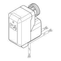
Details the M7410E actuator's use in fan-coil units, induction units, and zone control applications.

Design Features

Highlights microprocessor control, low power consumption, and self-adjusting close-off point for reliable operation.

Features

Specifications

Versions

Operation

Movement and Control Mechanism

Describes the actuator's screw spindle drive, gears, and magnetic clutch for torque limitation.

Automatic Synchronization Function

Explains the self-adjusting close-off point via automatic synchronization.

Mounting Position

Mounting

Adjustment Cap Removal

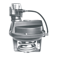
Instructions for removing the adjustment cap before mounting the actuator.

Manual Mounting Procedure

Guidance on mounting the actuator by hand without tools or excessive force.

Switch Selection

Electric Wiring

Input Signal Override

Manual Operation

Hexagonal Key Operation

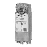
Details manual operation using a hexagonal key for specific models.

Safety Precautions for Manual Operation

Emphasizes disabling motor power to prevent valve damage during manual adjustments.

Commissioning Advice

Functional Check Procedure

Describes how to check actuator function by changing the input signal.

Direct;Reverse Switch Adjustment

Instructs on resetting the direct/reverse switch if travel direction is incorrect.

Auxiliary Switches

Switch Types and Functionality

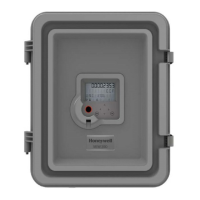
Explains fixed S1 and adjustable S2 auxiliary switches and their stem position activation.

Electric Wiring of Auxiliary Switches

Wiring Diagram Compliance

States that electrical installation must comply with wiring diagrams and specifies contact gap requirements.

Application Example: 2-Way-Valve

Illustrates auxiliary switch wiring for a 2-way valve controlling an appliance like a fan or pump.

Wiring for Other Valves

Provides wiring examples for various valve sizes (DN 15-20, DN 25-40, DN 15-40) and stem positions.

Dimensions

Housing Type B Dimensions

Presents dimensional drawings for the actuator's Housing Type B.

Housing Type C Dimensions

Presents dimensional drawings for the actuator's Housing Type C.

Related product manuals