M7410E SMALL MODULATING LINEAR VALVE ACTUATOR
5 EN0B-0097GE51 R1004
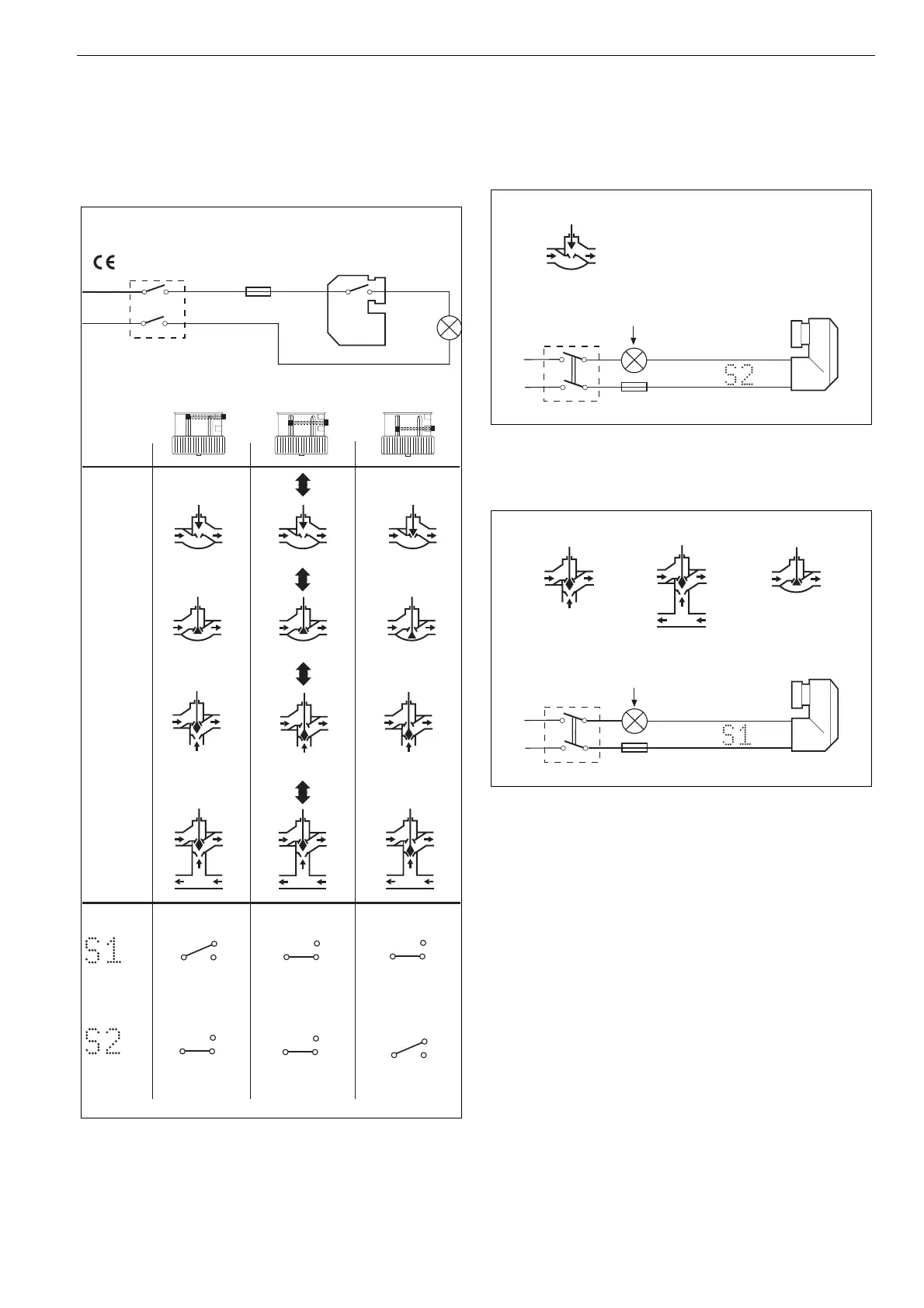
Electric Wiring of Auxiliary Switches
The electrical installation must comply with the wiring
diagram shown in Fig. 10. If the auxiliary switch is connected
to 230 Vac, a switch with a contact gap of at least 3 mm for
each pole must be fitted with the installation.
DN 15,
DN 20
DN 25 -
DN 40
DN 15 -
DN 40
DN 15 -
DN 20
(230 Vac only):
M7410E
max. 5 (1)A
230 Vac:
max. 100 mA
24 Vac:
BLUE
BROWN
BLACK
BLUE
BROWN
BLACK
BLUE
BROWN
BLACK
BLUE
BROWN
BLACK
BLUE
BROWN
BLACK
BLUE
BROWN
BLACK
ABAB
open
AB
close
AB
AAB
B
AAB
B
AAB
B
AAB
B
AB
AB
open
close
AAB
B
openclose
AAB
B
close
open
Fig. 10. Electric wiring of auxiliary switch
Application Example:
Switching Off an Electrical Appliance
2-Way-Valve
DN 15, DN 20
max. 5 (1)A
BLUE
BLACK
E. g. fan, pump etc.
Fig. 11. Electric wiring of auxiliary switch
All Other Valves
DN 15 - DN 40 DN 25 - DN 40DN 15 - DN 20
max. 5 (1)A
BLUE
BLACK
E. g. fan, pump etc.
Fig. 12. Electric wiring of auxiliary switch
 Loading...