XIO FAMILY OF SPECTRUM SYSTEM REMOTE INPUT/OUTPUT DEVICES
7 31-00360—01
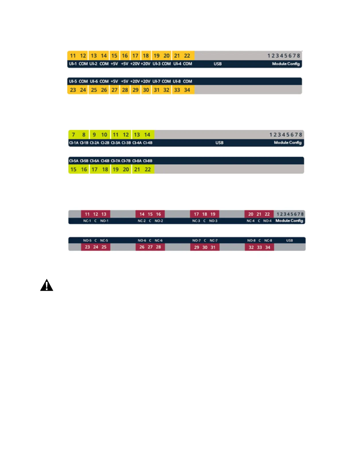
Fig. 10. Terminal Label/PIN configuration for the XIO-RIM-S, XIO-AOM-S, XIO-CIM-S and XIO-8IM-S.
Fig. 11. Terminal Label/PIN configuration for the XIO-RIMCT-S.
Fig. 12. Terminal Label/PIN configuration for the XIO-ROM-S, XIO-CCM-S-H and XIO-COM-S-H.
Electrical Shock Hazard
Can cause severe injury, death or property
damage.
Disconnect power supply and load power sources
before beginning wiring or making wiring
connections to prevent electrical shock or
equipment damage.
NOTE: For multiple controllers operating from a single
transformer, the same wire of the transformer
secondary must be connected to the same power
input terminal in each controller.
The total power draw for all modules sharing the
same transformer must not exceed 100VA.
HOA Switch LED Operation
For output modules equipped with HOA switches, the LED
will rapidly blink on and off if the HOA is in either the Hand
(H), or Off (O) positions to notify that the device is not
operating in automatic control. When the switch is in the
Auto (A) position, the LED will be continuously on or off, to
match the status of the output relay coil.
The position of the HOA switches is displayed on software
monitoring screens. Therefore, if the device is overridden,
you have a method of seeing that in the software. If
needed, alarms can be set up whenever loads are put into
override.
Wiring Method
Each terminal block can accommodate the following
gauges of wire:
• Single wire: from 22 AWG to 14 AWG solid or stranded
• Multiple wires: up to two 18 AWG stranded
NOTE: When attaching two or more wires to the same
terminal, other than 14 AWG (2.0 sq mm), be sure
to twist them together. Deviation from this rule
can result in improper electrical contact.

 Loading...


