AA-series Audio Amplifiers Manual for DVC-AO Applications — P/N 52526:B 8/13/2019 15
AA-100/AA-120 General Operation Amplifying Audio Messages
3.6 AA-100/AA-120 General Operation
During complete loss of primary (AC) power, the AA-100/AA-120 operates on secondary (battery) power. To conserve secondary
power, no LEDs light on the AA-100 or AA-120 while operating on batteries.
The amplifier does not indicate a trouble condition until 40 seconds after a fault occurs.
(shield)
(–)
(+)
(shield)
(–)
(+)
(–)
(+)
Earth
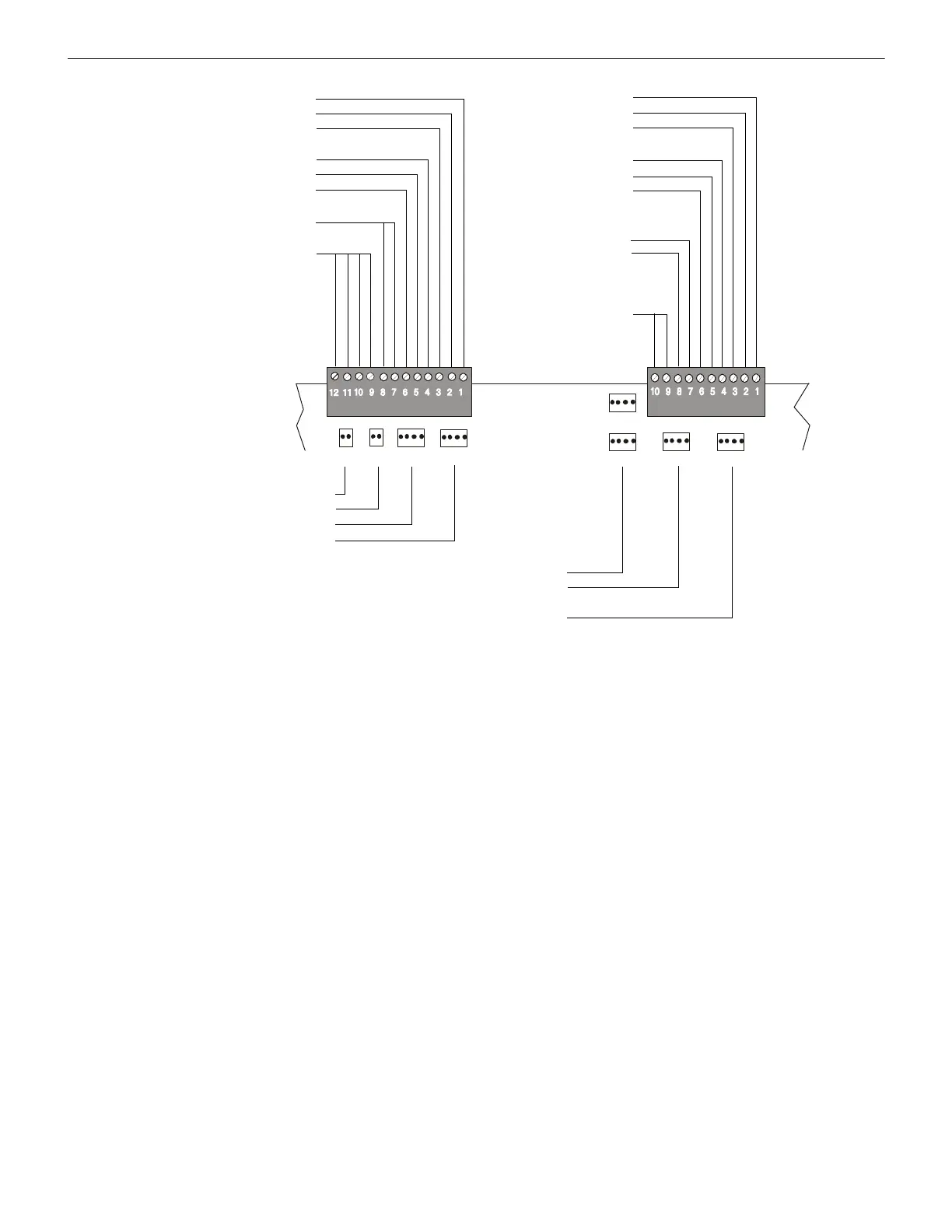
High Level
Audio Out
25 Vrms (AA-120)
High Level Audio
Return (Four-wire,
supervised)
(–)
(+)
(shield)
(–)
(+)
(shield)
Common
Trouble
Trouble In
Trouble Out
Low-level Audio In
Low-level Audio Thru
Backup High Level In
Backup High Level Out
High Level Audio Out
AA120upbrd.wmf
High Level
Audio Out
70.7 Vrms
(AA-100, see note)
Low-level
Audio In
Low-level
Audio Thru*
Note if using 70.7 Vrms speakers: Due to higher power dissipation at the 70.7 volt audio level, the 2 watt, 4.7K end of line resistors
supplied with the AA-100 Audio Amplifier must be used in place of the resistors supplied with the speaker-control devices. Systems
configured for 70.7 Vrms operation must use Class B wiring.
*Note: If not using Class A low-level audio return, an R-470 resistor assembly may be installed across P3, pins 4 and 5 of the last
directly connected device on the low-level audio riser; this may help to calibrate the audio amplifier.
Figure 3.9 AA-100 and AA-120 Upper Board Connections (power-limited)
 Loading...