AA-series Audio Amplifiers Manual for DVC-AO Applications — P/N 52526:B 8/13/2019 9
Power-Supply and Battery Requirements Product Overview
Retrofit Applications
When redesigning existing systems for compliance with UL 864 9th Edition, note the following functional replacements:
• AMG-1/E has been replaced by the DVC-AO.
• VCM-4RK and DCM-4RK have been replaced by SLC loop output control devices.
• The riser functions of FFT-7/7S have been integrated into Digital Voice Command systems as described in the main system manual;
the permanent master handset is provided by the TELH-1. (Note that where “F.F.T.” appears in print now, it serves as an acronym
for “firefighters’ telephone.)
2.3 Power-Supply and Battery Requirements
The installation manual for each fire alarm control panel (or its primary power supply if that is a separate document) provides calcula-
tions that must be done to determine standby and alarm DC current loads. Ampere-hour requirements must be calculated as well to deter-
mine battery size. The specific calculations may vary; use the instructions provided in your FACP/power supply documentation.
The following values are to be used in the FACP’s Power Supply Calculations:
• For AC Branch Circuit current requirements, allow 1.0 A current for each AA-30, and 1.85 A current for each AA-100 or AA-120.
• For calculating Secondary, non-fire alarm current draw, allow 0.045 A for each AA-30, and 0.050 A for each AA-100 or AA-120.
Do not include AA-series audio amplifiers in primary current-draw calculations, because they are calculated as power supplies
when AC power is available. (If AA-series audio amplifiers are not specifically listed in the manual for your compatible, UL-listed
FACP/power supply, enter this in the row provided for “Compatible devices not listed above”.)
• For calculating the Maximum Secondary Power fire alarm current draw, allow 3.0 A for each AA-30 and 7.3 A for each AA-100 or
AA-120. (Exclude amplifiers that are employed for backup.)
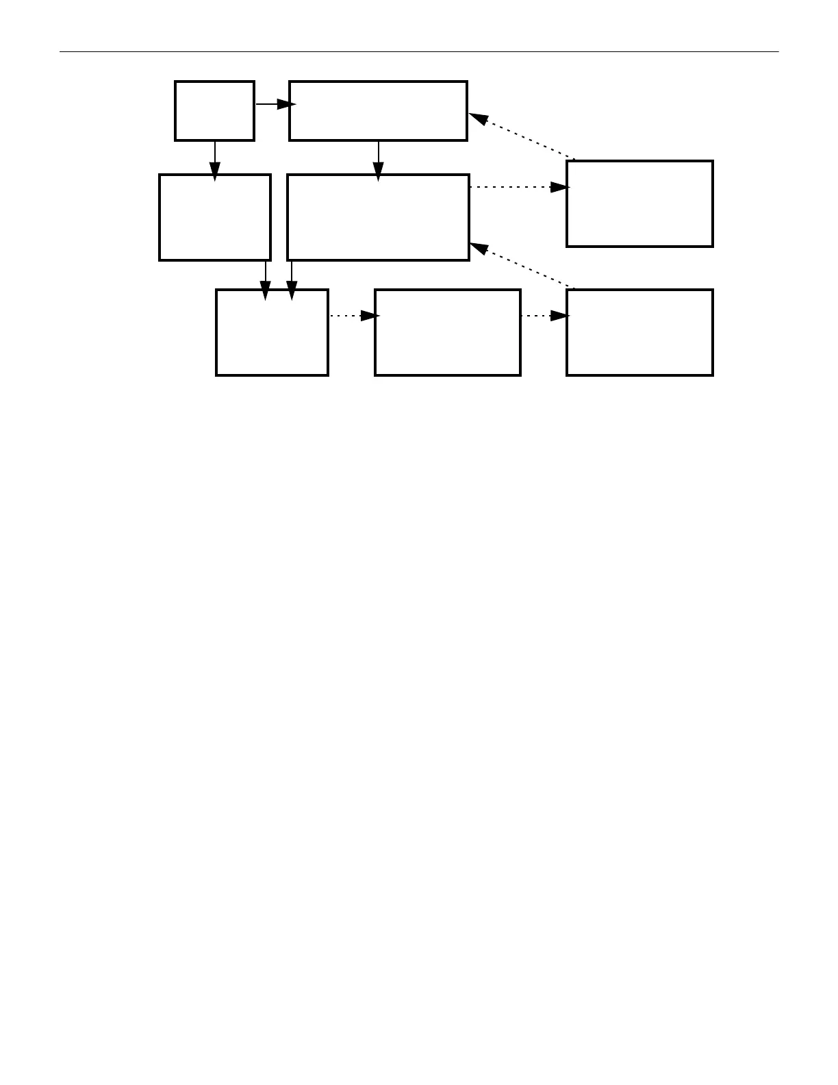
DVC-AO sends a low-level
analog audio message
to an AA-series audio amplifier.
AA-30, AA-100, or AA-120
amplifies the message and
sends a high-level analog audio
signal to the speaker-control module
(or group of modules).
CBE programming
turns on SLC devices
programmed as
speaker-control
modules.
FACP
receives
an alarm
Speaker-control
module turns on
and sends
high-level audio
to its speakers.
If additional speaker-control
modules are connected,
the others also turn on and
send the same message
to their speakers.
If optional Class X return is
connected, the last
speaker-control module
sends high-level audio
back to the audio amplifier.
If optional Class A return is
connected, the last AA-30,
AA-100, or AA-120 sends
low-level audio back to the
DVC-AO.
Figure 2.1 Product Overview
 Loading...