20 PSE Series Instruction Manual — P/N LS10227-000NF-E:B 3/29/2021
Installation Canadian Applications
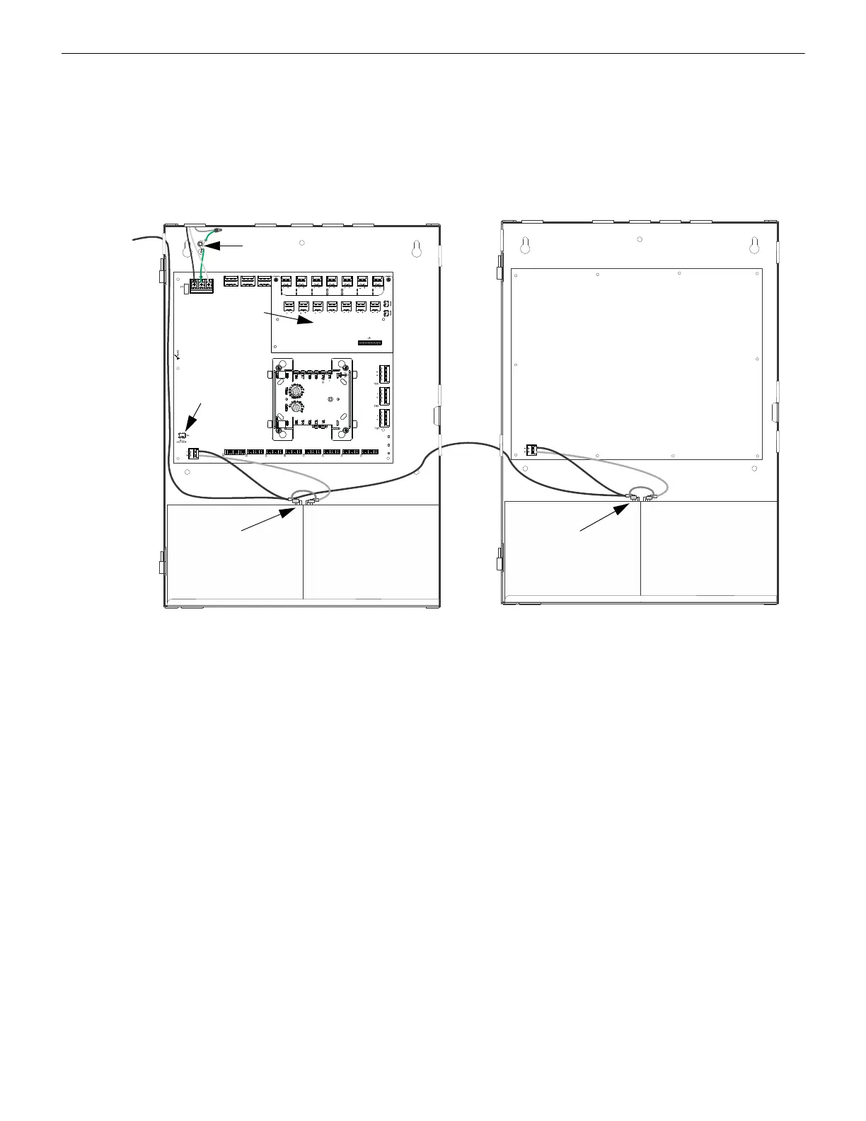
Ground Fault Detection
When connected to an FACP, the host FACP must monitor for all ground fault conditions.
There are three ways to monitor for ground faults when cascading multiple power supply units (up to four).
The negative (-) battery terminal of the PSE power supply must be connected to the negative (-) battery terminal of the host
FACP. Battery wiring is non-power-limited. Power-limited and non-power-limited wiring must be wired with a minimum of
0.25” spacing in between and enter/exit through different knockouts. When cascading multiple power supply units, continue
connecting the negative battery terminals, including FACP battery terminal. Ground faults must then be detected by the first PSE
in the chain. Disable ground fault detection on other PSE units by sliding SW1 to the left. Ensure ground fault detection is
enabled on PSE1, the first power supply from the FACP, by sliding SW1 to the right. 18 AWG wire minimum must be used.
NO NC C NO NC C
TB4
TB15
NO NC C
T
B
3
T
B
2
T
B
1
T
B
1
3
T
B
1
2
T
B
1
1
T
B
1
0
T
B
9
T
B
8
NAC1
AUX1
NAC2
AUX2
Host FACP Power Supply
optional
ZNAC-PS
converter
card
SW1 ground fault
detection switch
wire nut, ground
cables, and
ground stud
Figure 2.14 Canadian Applications Option 1
Battery -
Battery -
to next
negative
battery
terminal
 Loading...


