30 PSE Series Instruction Manual — P/N LS10227-000NF-E:B 3/29/2021
LED Indicators
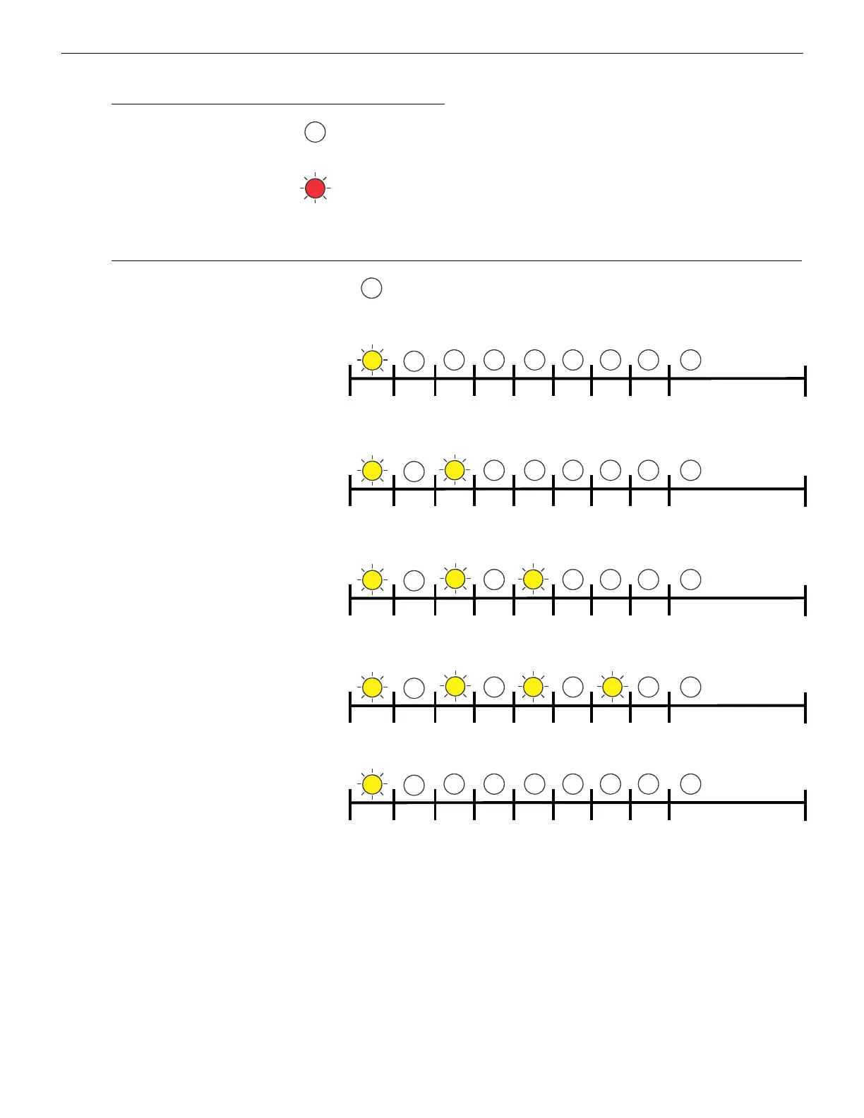
Output Circuit Status LEDs (red)
Output inactive LED is OFF
Output active LED is ON constant
Output Circuit Trouble LEDs (yellow)
No Fault LED is OFF
Fault Condition (Normal/Standby Mode):
Wire Supervision
Class A or B Open circuit
1 short blink (250ms)
Repeating LED blink pattern (non-diagnostic mode and diagnostic mode)
Fault Condition (Normal/Standby Mode):
Wire Supervision
Class A or B Short Circuit
2 short blinks (250ms)
Repeating LED blink pattern (non-diagnostic mode and diagnostic mode)
Fault Condition:
Aux Power Supervision
Class A Open circuit
(ZNAC-PS Circuit #1 and #2 only)
3 short blinks (250ms)
Repeating LED blink pattern (non-diagnostic mode and diagnostic mode)
Fault Condition:
Power limit condition (individual ckt overload)
4 short blinks per individual circuit (250ms)
Repeating LED blink pattern (non-diagnostic mode and diagnostic mode)
Fault Condition:
Power limit condition (panel overload)
4 short blinks on all output circuits (250ms)
Operating Mode Fault:
Power Supply not in Normal Operating mode
1 short blink from right to left across all output
circuits.
Set positions 9 and 10 on S1 to the ON
position.
Repeating LED blink pattern (non-diagnostic mode)
250ms
250ms
250ms
250ms
250ms
250ms
250ms
250ms
1000ms
pause
250ms
250ms
250ms
250ms
250ms
250ms
250ms
250ms
1000ms
pause
250ms
250ms
250ms
250ms
250ms
250ms
250ms
250ms
1000ms
pause
250ms
250ms
250ms
250ms
250ms
250ms
250ms
250ms
1000ms
pause
250ms
250ms
250ms
250ms
250ms
250ms
250ms
250ms
1000ms
pause
 Loading...


