EC7890 RM7890 · Edition 12.23
EN-7
4.2.1 Table 5. Static Checkout.
Test
No.
Test Jumpers
Voltme-
ter
Normal Operation
If Operation is Abnormal, Check the Items
Listed Below
1 – 3-L2 Line Voltage
1. Master switch.
2. Power connected to the master switch.
3. Overload protection (fuse, circuit breaker, etc.) has
not opened the power line.
2 – 6-L2 Line Voltage
1. Limits.
2. Burner control.
3 3-10 —
Ignition spark (if ignition transformer is
connected to terminal 10).
1. Watch for spark or listen for buzz.
a. Ignition electrodes are clean
b. Ignition transformer is okay.
4 3-8 —
1. Ignition spark (if ignition transformer is
connected to terminal 8).
2. Automatic pilot valve opens (if connec-
ted to terminal 8 or main valve if DSI
application).
NOTE: Refer to wiring diagram of system
being tested.
1. Watch for spark or listen for buzz:
a. Ignition electrodes are clean.
b. Ignition transformer is okay.
2. Listen for click or feel head of valve for activation:
a. Actuator, if used.
b. Pilot valve.
5 3-9 –
Automatic fuel valve(s) opens. (If using
direct spark ignition, check the second
stage fuel valve(s).)
Same as test number 4. If using direct spark ignition,
check the first stage fuel valve(s) instead of the pilot
valve.
6 3-4 – Alarm (if used) turns on. 1. Alarm.
FINAL
CAUTION!
Equipment Damage Hazard.
Can cause serious equipment damage.
After completing these tests, open the master switch, remove all test jumpers from the subbase terminals, and remove any
bypass jumpers from the low fuel pressure limits to prevent equipment damage.
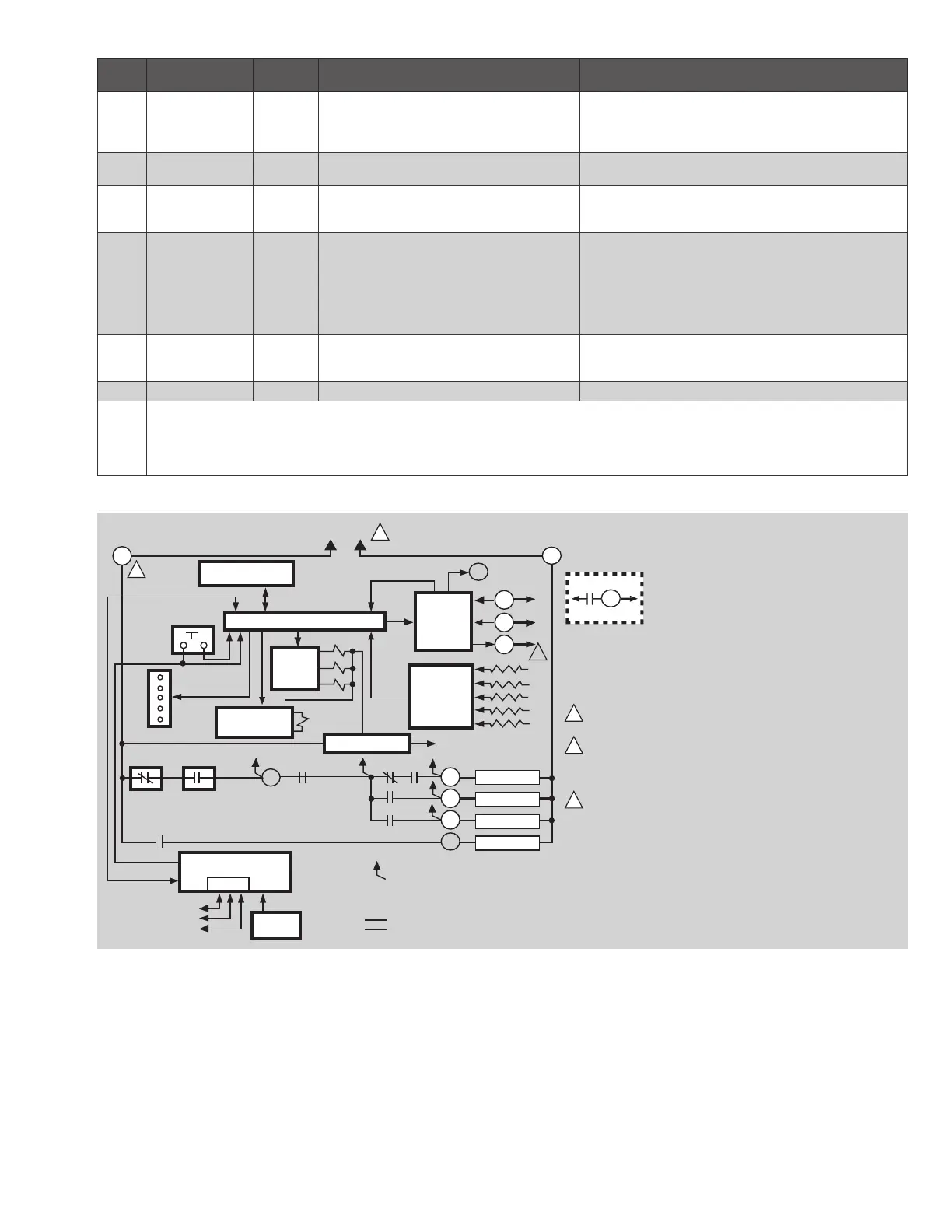
4.2.2 Fig. 1. Internal block diagram of the RM/EC7890
1K
1K1
2K2
RS485
1
2
3
L1
L2
3
N. O.
6
5K1
4K1
2K1
10
8
9
4K
3K
2K
F
G
22
3K1
4
L2
M11586A
F
RM7890C
1
2
2
1
3
3
CONFIGURATION
JUMPERS
MICROCOMPUTER
RESET
PUSH-
BUTTON
STATUS LEDs
SAFETY RELAY
CIRCUIT
POWER SUPPLY
OPTIONAL KEYBOARD
DISPLAY MODULE
PLUG-IN
FLAME
AMPLIFIER
RELAY
DRIVE
CIRCUIT
CONTROL
POWER
TEST
JACK
REMOTE
RESET
DDL
DDL
COMMUNICATIONS
IGNITION
PILOT
MAIN VALVE
INDICATES FEEDBACK SENSING
TO RELAY STATUS FEEDBACKAND LINE VOLT INPUTS
FIELD WIRING
INTERNAL WIRING
RELAY
STATUS
FEEDBACK
AND LINE
VOLTAGE
INPUTS
LIMITS CONTROLLER
FLAME SIGNAL
TEST
(HOT)
NUMBERS IN CIRCLES ARE RELAY MODULE
TERMINAL NUMBERS.
PROVIDE DISCONNECT MEANS AND
OVERLOAD PROTECTION AS REQUIRED.
120 VAC, 50/60 HZ (RM7890); 220-240 VAC,
50/60 HZ (EC7890) POWER SUPPLY.
EC7890 REQUIRES A 220/240 VAC TO 120 VAC,
10VA, STEPDOWN TRANSFORMER (NOT
SUPPLIED) WHEN USING C7012E, F; C7061A,
AND C7076A FLAME DETECTORS. NOT APPLICABLE
FOR C7061A1020, C7061A1079, C7061F1003 and
C7061F1011-N.
ALARM
 Loading...