Do you have a question about the Honeywell EC7850A Series and is the answer not in the manual?
Covers critical warnings and general steps for safe product installation.
Steps to verify wiring, external devices, and proper operation before starting.
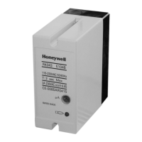
The Honeywell EC7830A, RM7830A, EC7850A, and RM7850A are microprocessor-based integrated burner controls designed for automatically fired gas, oil, or combination fuel applications. The EC/RM7850A models are for full modulation, while the EC/RM7830A models are for on/off applications. Each system comprises a relay module, subbase, amplifier, and purge card. Optional components include a keyboard display module (KDM), a Data ControlBus™ Module, and remote display mounting.
These relay modules provide automatic burner sequencing, flame supervision, system status indication, and self-diagnostics with troubleshooting capabilities. Text readout on the Keyboard Display Module is available in multiple languages. The devices are SIL 3 Capable in a properly designed Safety Instrumented System, as per form 65-0312 for Certificate Agreement.
Installation requires careful adherence to instructions to prevent product damage or hazardous conditions. The installer must be a trained, experienced flame safeguard service technician. Wiring must comply with all applicable codes, ordinances, and regulations, including NEC Class 1 (Line Voltage) wiring. Loads connected to the EC/RM7830A and EC/RM7850A must not exceed the ratings specified on the relay module label or in the specifications. Limits and interlocks must be rated to simultaneously carry and break current to the ignition transformer, pilot valve, and main fuel valve(s). All external timers must be listed or component-recognized by authorities having proper jurisdiction.
The subbase can be mounted in any position except horizontally with bifurcated contacts pointing down (vertical is recommended to maintain maximum ambient temperature rating). For CE devices, the Q7800 must be mounted inside a control cabinet. Adequate clearance for service, installation, access, or removal of the relay module, KDM, flame amplifier, signal voltage probes, Run/Test Switch, and electrical connections is essential.
Series 1000 Relay Modules (product codes starting with '1') are compatible with Q7800A1003/U and Q7800A1005/U subbases. Series 2000 Relay Modules (product codes starting with '2') require Q7800A2003/U and Q7800A2005/U subbases. Any 1000 Series Relay Module with a Software Revision level of "5" or greater is compatible with all subbase models, including Q7800A1005/U, Q7800B1003/U, Q7800A2005/U, and Q7800B2003/U. New 2000 series relay modules are only compatible with Q7800A2005/U and Q7800B2003/U subbases and are not backward compatible with 1000 series subbases.
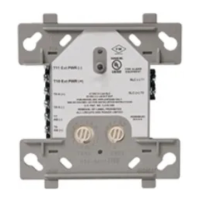
For remote mounting of the KDM and/or Remote Reset Module to comply with CE EN60730, electrical separation using insulation equivalent to double or reinforced insulation is necessary. This can be achieved by optically isolating communication/remote reset lines from the control cabinet or by providing physical separation using electrical conduit and a 204718A Remote Display Cover Assembly or other NEMA4 class enclosure.
The relay modules follow specific operating sequences (Initiate, Standby, Purge, Ignition Trials, Pilot Stabilization, Main Trial, Run, Postpurge), with LED indicators for POWER, PILOT, FLAME, MAIN, and ALARM.
Located on the top side of the relay module, this switch allows altering the burner sequence. It can hold the burner in PURGE at high or low fire, stop the PURGE timing, or stop the PILOT STAB. timer for adjustments. In RUN, it drives the firing rate motor to low fire.
The relay module has three site-configurable jumpers (JR1, JR2, JR3) for First Safety Time, Main Trial Time, and Airflow Switch. These settings are read at startup and locked into internal memory after 200 hours of main valve operation. Changing jumpers after this lock-in period will cause the module to lock out.
Before installing the relay module on the wiring subbase, a static checkout must be performed. This verifies correct wiring of the Q7800 Wiring Subbase and proper operation of external controllers, limits, interlocks, actuators, valves, transformers, motors, and other devices. This involves opening the master switch, installing jumper wires between subbase terminals, closing the master switch, and reading voltage measurements. If operation is abnormal, specific items (master switch, power connection, overload protection, preignition interlocks, alarm, recycle limits, burner control, fan circuit, running limits, airflow switch, ignition electrodes, ignition transformer, pilot valve, actuator) should be checked.
The document provides detailed troubleshooting steps for abnormal operations during static checkout, including specific checks for issues like no voltage, abnormal operation, incorrect wiring, damaged wires, or faulty components.
The module will lock out under various conditions during different operating periods:
The device should be accessible only to authorized personnel and installed in an enclosed cabinet with restricted access. All wiring should be physically secure. The Run/Test switch label/seal provides physical protection to prevent unauthorized access and detect tampering.
Critical device functionality lines (DDL, Modbus) must be physically protected from public access. Modbus RS-485 & DDL protocols do not support security features; only DDL devices should be connected to the Burner Controller DDL line for DDL interface.