Do you have a question about the Honeywell NOTIFIER FRM-1 and is the answer not in the manual?
Lists normal operating voltage, current draw, temperature, humidity, and dimensions.
Provides pre-installation guidance, warnings, and contact information.
Explains the FRM-1 module's function, use in two-wire systems, and rotary switches.
Specifies the need for connection to a compatible Notifier system control panel.
Details how to mount the FRM-1 module to electrical boxes or housings.
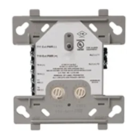
Covers wiring practices, use of barriers, and terminal connections.
Details current, voltage, and load descriptions for relay contacts.
Illustrates the signal line circuit and module connections.
The FRM-1 Relay Control Module is an intelligent, two-wire device designed for use in compatible fire alarm systems. Its primary function is to enable a control panel to switch discrete contacts by code command. This module is equipped with built-in rotary switches, allowing for the individual address of each module to be selected, which is crucial for its integration into an intelligent system.
The FRM-1 module contains two isolated sets of Form-C contacts. These contacts operate as a Double-Pole, Double-Throw (DPDT) switch, meaning they can switch between two different circuits. The relay contacts are rated for various current and voltage levels, supporting both resistive and inductive loads, and are suitable for both non-coded and coded applications. This versatility allows the module to control a wide range of external devices, such as door holders, fans, or other auxiliary equipment, based on commands from the control panel.
A key feature of the FRM-1 is its ability to replace a CMX-2 module that has been configured for Form-C operation, providing a direct upgrade path or alternative for existing installations. The module also includes a panel-controlled LED indicator, which provides visual feedback on its operational status, aiding in troubleshooting and system monitoring.
The FRM-1 is designed for straightforward installation and integration into fire alarm systems. It mounts directly to standard 4-inch square electrical boxes, requiring a minimum depth of 2 1/8 inches. Notifier also offers surface-mounted electrical boxes (SMB500) and a barrier (CB500) for specific installation requirements. The module can also be installed in a DNR(W) duct housing, expanding its application possibilities.
For installations where nonpower-limited applications are involved, the CB500 Module Barrier is essential. This barrier ensures compliance with UL requirements for the separation of power-limited and nonpower-limited terminals and wiring. The barrier is inserted into the junction box, and the control module is then attached to the barrier, with power-limited wiring placed in the isolated quadrant of the barrier. This attention to wiring separation is critical for maintaining system integrity and safety.
The module's address is set using built-in rotary switches, which are clearly labeled for TENS and ONES, allowing for easy and accurate configuration according to job drawings. Wiring connections are made to clearly marked terminals, and it is recommended to strip wires to an appropriate length (1/4" to 3/8") to ensure secure connections under the clamping plate without protruding beyond the terminal block area. The manual explicitly advises against looping wires under terminals, emphasizing the importance of breaking wire runs to provide supervision of connections.
The FRM-1 is compatible with Notifier system control panels, and a list of compatible panels is available from Notifier to ensure proper operation. The module's design allows for flexible integration into various system architectures.
While the FRM-1 is designed for reliable operation, certain considerations are important for maintenance and system integrity. The module itself does not supervise the controlled circuits connected to its relay contacts. This means that external supervision mechanisms may be required for the devices controlled by the FRM-1 if supervision is a system requirement.
Before installation or any maintenance work, it is crucial to inform the operator and local authority that the system will be temporarily out of service. Disconnecting power to the control panel before installing or servicing the modules is a mandatory safety precaution.
All relay switch contacts are shipped in a standby (open) state. However, due to potential transfer during shipping, it is essential to ensure that the switch contacts are in their correct state by making the modules communicate with the control panel before connecting any circuits controlled by the module. This step helps prevent unexpected activation or deactivation of connected devices.
The module's robust design and clear labeling of terminals and address switches simplify troubleshooting and maintenance tasks. The panel-controlled LED indicator provides immediate visual feedback, which can help in quickly identifying the module's status during system checks. The detailed wiring diagrams provided in the manual further assist technicians in correctly installing and maintaining the module, ensuring long-term reliability and compliance with applicable codes and regulations.
| Operating Voltage | 24 VDC |
|---|---|
| Operating Temperature | 32°F to 120°F (0°C to 49°C) |
| Humidity | 10% to 93% non-condensing |
| Contact Configuration | Single Pole Double Throw (SPDT) |
| Contact Rating | 2 A @ 30 VDC (resistive) |
| Contact Type | Form C |