Do you have a question about the Honeywell HPSR104 and is the answer not in the manual?
Lists items included in the product package for installation.
Highlights critical safety warnings for electrical shock and installation procedures.
Instructions for mounting the panel using wall-mounted screws.
Steps for mounting the panel onto a DIN rail.
Explains the wiring terminal for 120V/60Hz/1Ph power input to the panel.
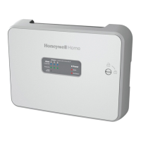
Details the function of advanced status lighting and indicator LEDs on the panel.
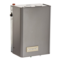
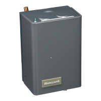
Information on compatibility and wiring of common zone pumps.
Discusses compatibility with various thermostat types and wiring terminals.
Explains the priority operation function and its control logic.
Describes the location and purpose of the grounding bar.
Explains the function of indicator LEDs for T-stat Call, Pump On, DHW Priority, Power, Boiler, End Switch.
| Switching Mode | Zero Cross |
|---|---|
| Contact Form | SPST-NO |
| Category | Relays |
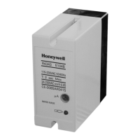
| Type | Solid State Relay |
| Output Voltage | 24 ~ 280 VAC |
| Contact Rating | 1A at 280V AC |
| Ambient Temperature | -30°C ~ +80°C |