EasyManua.ls Logo

Honeywell HPSR103 User Manual

Honeywell HPSR103
12 pages
To Next Page IconTo Next Page
Page #1 background imageLoading...
Page #1 background image
INSTALLATION INSTRUCTIONS
33-00331EF-05
HPSR10*
HONEYWELL HYDRONIC PRO
SWITCHING RELAY PANEL
WHAT'S IN THE BOX?
Hydronic Zone Panel
Mounting Hardware (3 Screws and 3 Wall Anchors)
1, 2-Amp Fuse; 1, 6-Amp Fuse
Install Manuals (English & French)
CAUTION
1. Disconnect power supply before beginning
installation to prevent electrical shock or
equipment damage.
2. Use copper conductors only.
3. Use only NEC Class 1 wire for all line voltage
wiring connections. Class 1 wires must be
rated for at least 167 °F (75 °C).
4. For installation by professionals only.
PANEL SPECIFICATIONS
Table 1.
NOTES:
All circulator relay connections, including ZC/ZR, are rated for 5A full load and 30A locked rotor (1/6 to 1/2HP
depending on technology) at 120VAC. Check circulator plate ratings to ensure full load current is not exceeded.
End switch connections are rated 24V, 1 Amp.
All thermostat connections supply a 24V Class 2 output.
Model Zones Transformers Input Power
Maximum
Combined
Load
Pump
Fuse
Priority
Zone
Control
Type 1 Enclosure
Width Height Depth
HPSR103 3 (1) 24V 40VA 120VAC, 60Hz, 1 15 amps 6 Amp Yes 11-3/4" 8-3/4" 2-1/8"
HPSR104 4 (1) 24V 40VA 120VAC, 60Hz, 1 20 amps 6 Amp Yes 11-3/4" 8-3/4" 2-1/8"
HPSR106 6 (1) 24V 40VA 120VAC, 60Hz, 1 20 amps 6 Amp Yes 11-3/4" 8-3/4" 2-1/8"
Question and Answer IconNeed help?

Do you have a question about the Honeywell HPSR103 and is the answer not in the manual?

Honeywell HPSR103 Specifications

General IconGeneral
Mechanical Life10, 000, 000 operations
Mounting TypeDIN Rail
Coil Voltage24 VDC
Release Time10ms max
Insulation Resistance100MΩ min at 500V DC
Dielectric Strength2.5 kV
Electrical Life100, 000 operations

Summary

Installation Instructions

What's in the Box

Lists items included in the product package.

Caution

Lists essential safety precautions for installation and electrical handling.

Panel Specifications

Mounting

Hang Hole Flow Mounting

Describes how to mount the panel using hanging holes.

DIN Rail Flow Mounting

Describes how to mount the panel using a DIN rail.

Wiring and Setup

Power Input

Explains the 120V/60Hz/1Ph power connection terminal.

Status Indicators

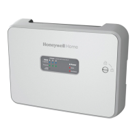
Details the panel's status lights for power and transformer status.

Zone Pump Compatibility

Discusses compatibility with common zone pumps and wiring.

Thermostat Compatibility

Covers compatibility with various thermostat types and wiring.

Priority Override Function

Explains the panel's priority operation and override logic.

Grounding

Describes the location and purpose of the grounding bar.

Standard Wiring Layout

Boiler Controls

Troubleshooting

Status Label and LEDs

Explains the status indicator label and LED colors for troubleshooting.

Regulatory Information

States compliance with FCC rules for device operation.

5-Year Limited Warranty

Outlines the terms and duration of the product warranty.

Related product manuals