Do you have a question about the Honeywell EC7890B1028 and is the answer not in the manual?
Describes the RM/EC7890 Relay Modules as microprocessor-based integrated burner controls for single burner applications.
Covers general wiring practices, wire routing, and maximum wire lengths for various connections.
Outlines the procedure to verify subbase wiring and external component operation before installing the relay module.
Provides step-by-step instructions and precautions for conducting the static checkout tests.
Illustrates the wiring connections for the subbase and provides an operating sequence chart for the RM/EC7890.
Lists conditions under which the RM/EC7890 will initiate a safety shutdown or lockout.
Details the various operating sequences of the RM/EC7890, including Initiate, Standby, and Run phases.
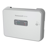
The Honeywell RM7890A, B/EC7890B Relay Modules are advanced microprocessor-based integrated burner controls designed for on/off automatically fired gas, oil, or combination fuel single burner applications. These modules serve as a replacement for the RA890F, G, H Protectorelay® Primary Control. The RM/EC7890 System comprises a relay module, a subbase, and an amplifier, with optional features such as a 2-line VFD or 4-line LCD Keyboard Display Module and remote display mounting.
The primary functions of the RM/EC7890 include automatic burner on/off sequencing, flame supervision, system status indication, system or self-diagnostics, and troubleshooting capabilities. These controls are designed to ensure safe and efficient burner operation.
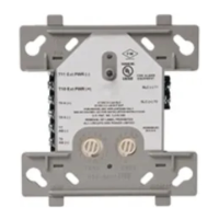
Installation of the RM/EC7890 involves careful consideration of wiring and mounting. The subbase can be mounted in any position except horizontally with the bifurcated contacts pointing down, with the standard vertical position being recommended to maintain maximum ambient temperature ratings. Adequate clearance for servicing, installation, and removal of the relay module, Expanded Annunciator, Keyboard Display Module, flame amplifier, flame amplifier signal voltage probes, Run/Test Switch, electrical signal voltage probes, and electrical field connections is crucial. For surface mounting, the subbase's back serves as a template for drilling pilot holes, and it is secured with four no. 6 screws.
Wiring connections for the relay modules are unique and require adherence to specific diagrams for individual subbase wiring. All wiring must comply with applicable codes, ordinances, and regulations, including NEC Class 1 (Line Voltage) wiring. Loads connected to the RM/EC7890 must not exceed specified limits. Limits and interlocks must be rated to simultaneously carry and break current to the ignition transformer, pilot valve, and main fuel valve(s). External timers must be listed or component-recognized by authorities. For on-off gas-fired systems, some authorities prohibit wiring limit or operating contacts in series between the flame safeguard control and the main fuel valve(s). Two flame detectors can be connected in parallel, with exceptions for the C7927 Ultraviolet Detector and C7915 Infrared Detector.
The equipment generates, uses, and can radiate radio frequency energy. If not installed and used according to instructions, it may cause interference with radio communications. It has been tested to comply with Class B computing device limits under Part 15 of FCC rules, designed to provide reasonable protection against interference in a commercial environment. In residential areas, users may need to take measures to correct interference at their own expense.
For proper remote wiring of the Keyboard Display Module (KDM), Data ControlBus Module™, or Extension Cable Assembly, specific instructions must be followed. The power supply must be disconnected from the main disconnect before installation to prevent electrical shock and equipment damage. Recommended wire routing dictates that high voltage ignition transformer wires should not run in the same conduit as flame detector, Data ControlBus Module™, or Remote Reset Module wiring. Flame detector leadwires without armor cable should be enclosed in metal cable or conduit.
The KDM, being powered from a low voltage, energy-limited source, can be mounted outside a control panel if protected from mechanical damage. A 13 Vdc power supply is required when more than one KDM is used. Maximum wire lengths are specified for RM/EC7890 leadwires, flame detector leadwires, Remote Reset leadwires, and Data ControlBus Module™™ cable length, which depends on the number of system modules, noise conditions, and cable type. The KDM or Data ControlBus Module™™ for remote mounting must be wired in a daisy chain configuration, with termination resistors required for connections over 100 feet. Recommended grounding practices emphasize providing a low impedance earth ground connection to the control panel, using wide straps or brackets for ground conductors, and ensuring mechanically tightened joints are free of nonconductive coatings. Signal ground for the Keyboard Display Module and Data ControlBus Module™™ involves grounding the shield of the signal wire to the signal ground terminals of each device, connecting the shield at both ends of the daisy chain to earth ground.
Maintenance features include a static checkout procedure performed before installing the RM/EC7890 on the subbase. This verifies correct wiring of the Q7800 Wiring Subbase and proper operation of external controllers, limits, interlocks, actuators, valves, transformers, motors, and other devices. During static checkout, all manual fuel shutoff valves must be closed, and extreme care must be taken as line voltage is present on most terminal connections. The master switch must be open before installing or removing jumpers on the subbase, and all test jumpers must be removed before proceeding to the next test. Faulty limits and interlocks must be replaced, not bypassed. A dielectric test should not be performed with the RM/EC7890 installed, as internal surge protectors could break down and damage the unit.
The RM/EC7890 provides customary flame safeguard functions, along with advancements in safety, annunciation, and system diagnostics. Safety shutdowns (lockouts) occur under various conditions, such as AC line power errors, configuration jumper changes, flame signal presence during standby, internal system faults, main valve energization during specific periods, and absence of flame at the end of the Pilot Flame Establishing Period (PFEP).
The operating sequence includes an INITIATE period, where the module verifies voltage and frequency tolerances. If tolerances are not met, a hold condition is initiated, leading to lockout if not corrected. Causes for hold conditions include AC line dropout detection, AC line noise, and brownouts. The STANDBY period follows, where the RM/EC7890 awaits a call for heat, ensuring all circuits are in the correct state. The Normal Start-Up Safe Start Check verifies no flame or flame simulating condition exists before proceeding to the Ignition Trial. During Ignition Trials, the pilot valve and ignition transformer are energized, and flame must be proven within the PFEP. Once flame is proven, ignition is de-energized, and the main valve is energized, entering the RUN period until the demand is satisfied or a limit opens.
The RM/EC7890 features selectable site-configurable jumpers, which can be clipped and removed to enhance safety levels or modify operational parameters, such as the Pilot Flame Establishing Period (PFEP) and Flame Failure Action (Relight or Lockout). Clipping and removing a jumper after 200 hours of operation results in a hard lockout.
For safety and security, the device should be accessible only to authorized personnel. Installation in publicly accessible places is not recommended to prevent unwanted or potentially unsafe changes. Locking the device in an enclosed cabinet with access restricted to approved and trained personnel is advised. Physical protection, such as a Run/Test switch label/seal, is intended to prevent and detect unauthorized access. Critical device functionality conducts, like DDL and Modbus lines, must be physically protected. Modbus RS-485 protocols do not support security features, and only Honeywell proprietary DDL devices should be connected to the Burner Controller DDL line. Copying and reverse engineering are prohibited by law.
At the end of its product life, the device and its packaging should be disposed of in a corresponding recycling center, not with usual domestic refuse, and should not be burned. Old units can be returned to the manufacturer for proper disposal according to waste legislation requirements.