EC7890 RM7890 · Edition 12.23
EN-4
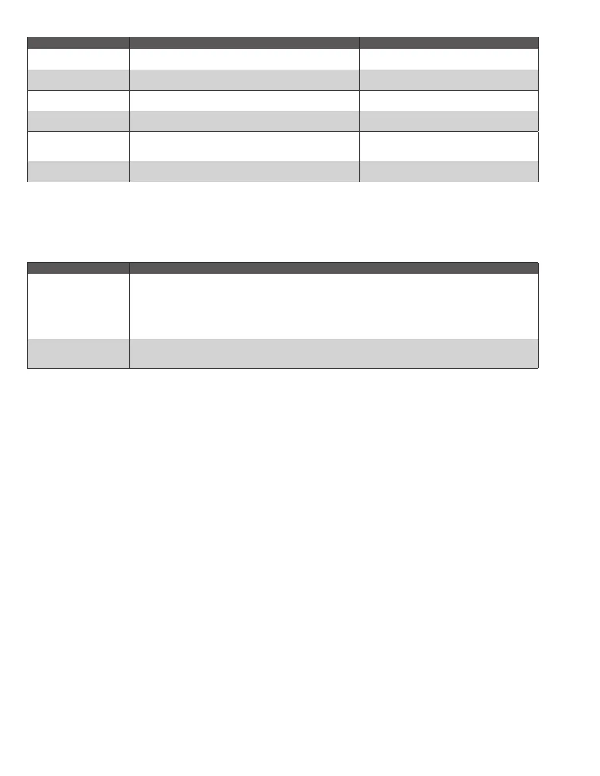
3.5.1 Table 1: Recommended Wire Sizes and Part Numbers.
Application Recommended Wire Size Recommended Part Numbers
Line Voltage Terminals
14, 16, or 18 AWG (0.75, 1.5 or 2.5mm
2
) copper conduc-
tor, 600 volt insulation, moisture-resistant wire.
TTW60C, THW75C, THHN90C.
Keyboard Display
Module KDM
a
22 AWG (0.34mm
2
) two-wire twisted pair with ground, or
five-wire.
Belden 8723 shielded cable or equivalent.
Data ControlBus™
Module
22 AWG (0.34mm
2
) two-wire twisted pair with ground, or
five-wire.
Belden 8723 shielded cable or equivalent.
Remote Reset Module
22 AWG (0.34mm
2
) two-wire twisted pair, insulated for
low voltage.
–
Communications
Interface ControlBus™
Module
22 AWG (0.34mm
2
) two-wire twisted pair with ground. Belden 8723 shielded cable or equivalent.
13 Vdc full wave rectified
transformer power input
18 AWG (0.75mm
2
) wire insulated for voltages and
temperatures for given application.
TTW60C, THW75C, THHN90C.
a
The KDM, Data ControlBus™ Module (for remote mounting or communications) or Communication Interface Control-Bus™ Module
must be wired in a daisy chain configuration, (1(a)-1(a), 2(b)-2(b), 3(c)-3(c)). The order of interconnection of all the devices listed
above is not important. Be aware that modules on the closest and farthest end of the daisy chain configuration string require a 120
ohm (1/4 watt minimum) resistor termination across terminals 1 and 2 of the electrical connectors for connections over 100feet
(30.5 meters).
3.5.2 Table 2. Recommended Grounding Practices.
Ground Type Recommended Practice
Earth ground (subbase
and relay module).
1. Use to provide a connection between the subbase and the control panel of the equipment. Earth
ground must be capable of conducting enough current to blow the 15A fuse (or breaker) in the event of an
internal short circuit.
2. Use wide straps or brackets to provide minimum length, maximum surface area ground conductors. If a
leadwire is required, use 14 AWG copper wire.
3. Make sure that mechanically tightened joints along the ground path are free of nonconductive coatings
and protected against corrosion on mating surfaces.
Signal ground (Keyboard
Display Module, Data
ControlBus Module™
Use the shield of the signal wire to ground the device to the signal ground terminals—3(c)—of each
device. Connect the shield at both ends of the daisy chain to earth ground.
 Loading...