EC7830A, RM7830A, EC7850A, RM7850A 7800 SERIES RELAY MODULES
17 32-00198—01
SETTINGS AND
ADJUSTMENTS
Selectable Site-Configurable
Jumpers
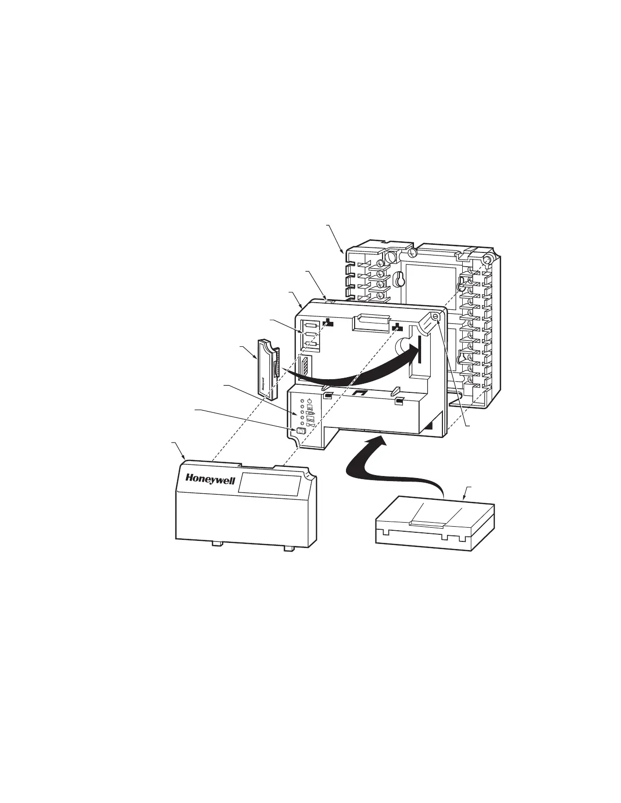
The relay module has three site-configurable jumper
options, see Fig. 6 or 7 and Table 7. If necessary, clip the
site-configurable jumpers with side cutters and remove
the resistors from the relay module. The relay module
reads the settings of these configuration jumpers at
startup. After 200 hours of main valve operation, the relay
module locks the jumper settings into internal memory. If
these jumpers are changed after the 200 hours occur, the
relay module locks out. This safety function assures that
the relay module cannot be modified after it is installed in
a particular location.
If JR3 (Airflow Switch) is intact (no Airflow Switch), then a
jumper must be installed between terminals 6 and 7. If
JR3 is clipped (Airflow Switch is present), the relay module
locks out if it detects a jumper between terminals 6 and 7.
SERVICE NOTE:Clipping and removing a site-configurable jumper enhances the level of safety.
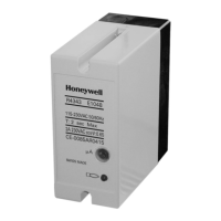
Fig. 6. EC/RM7830A and EC/RM7850A Relay Modules exploded view.
HONEYWELL
DUST
COVER
PURGE
TIMER
WIRING
SUBBASE
(Q7800A1005
plastic panel
mount version)
CAPTIVE
MOUNTING
SCREW
RUN/TEST
SWITCH
CONFIGURATION
JUMPERS
RELAY
MODULE
SEQUENCE
STATUS
LED PANEL
RESET
BUTTON
FLAME
AMPLIFIER
BURNER CONTROL
M15187B
 Loading...