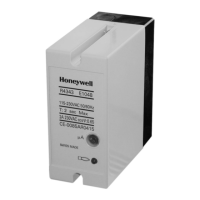
EC7830A, RM7830A, EC7850A, RM7850A 7800 SERIES RELAY MODULES
32-00198—01 10
3. Make sure no subbase wiring is projecting beyond
the terminal blocks. Tuck in wiring against the back
of the subbase so it does not interfere with the knife
blade terminals or bifurcated contacts.
IMPORTANT
Install the relay module with a plug-in motion
rather than a hinge action.
4. Mount the relay module by aligning the four L
shaped corner guides and knife blade terminals with
the bifurcated contacts on the wiring subbase and
securely tightening the two screws without
deforming the plastic.
STATIC CHECKOUT
After checking all wiring, perform this checkout before
installing the relay module on the wiring subbase. These
tests verify that the Q7800 Wiring Subbase is wired
correctly and the external controllers, limits, interlocks,
actuators, valves, transformers, motors and other devices
are operating properly.
For further checkout and troubleshooting, see form 65-
0229.
a
See Table 2.
b
Honeywell has tested this output at 9.8A at PF = 0.5, 58.8A inrush for 100,000 cycles (EN298 approval does not require
this test).
c
2000 VA maximum connected load to relay module.
d
1A, 10A inrush for 5000 cycles; carry 5A for 250,000 cycles.
e
220/240 Vac to 120 Vac, 10 VA stepdown transformer (not provided) must be used to drive the shutter. Transformer
does not apply to UV flame sensor models C7061A1020, C7061A1079 and C7061F1003 (combined with R7861-series
flame amplifiers), which have internal selectable terminal block to connect 230V shutter output directly.
Table 3. EC7830A/RM7830A Terminal Ratings.
Termina
l No. Abbreviation Description
Ratings
RM7830A (120 Vac) EC7830A (220/230/240 Vac)
G—
Flame Sensor Ground
a
——
Earth G —
Earth Ground
a
——
N — Line Voltage Common
(Neutral)
——
3 AL Alarm (Normally Open) 1A, 10A inrush for 5000
cycles.
1A, 10A inrush for 5000 cycles.
4 FAN Burner/Blower Motor
4A at PF = 0.5, 20A inrush.
b
4A at PF = 0.5, 20A inrush.
5 L1 Line Voltage Supply (L1) 120 Vac(+10%/-15%), 50/60
Hz (±10%).
c
220 to 240 Vac (+10%/-15%),
50/60 Hz (±10%).
c
6 RT Limits and Burner Control 1 mA 1 mA maximum
7 LD2 Airflow Switch Input 5A. 5A.
8 PV1 Pilot Valve 1 (Interrupted) 4A at PF = 0.5, 20A inrush. 4A at PF = 0.5, 20A inrush.
9 MV Main Fuel Valve 4A at PF = 0.5, 20A inrush. 4A at PF = 0.5, 20A inrush.
10 IGN Ignition 2A at PF = 0.2. 2A at PF = 0.2.
F (11) — Flame Signal 60 to 220 Vac, current limited. 60 to 220 Vac, current limited.
12 to 15 Not Used.
16 — Control Voltage
120 Vac (+10%/-15%).
d
220 to 240 Vac (+10%/-15%).
d
17 ES2 Preignition Interlock Input 1 mA.
1 mA.
d
18 to 19 Not Used.
20 LOS Lockout Input. 1 mA. 1 mA.
21 PV2 Pilot Valve 2 (intermittent) 4A at PF = 0.5, 20A inrush. 4A at PF = 0.5, 20A inrush.
22 SHTR Shutter Shutter drive for dynamic self-
check flame sensor.
Shutter drive for dynamic
self-check flame sensor.
e
 Loading...