EC7830A, RM7830A, EC7850A, RM7850A 7800 SERIES RELAY MODULES
9 32-00198—01
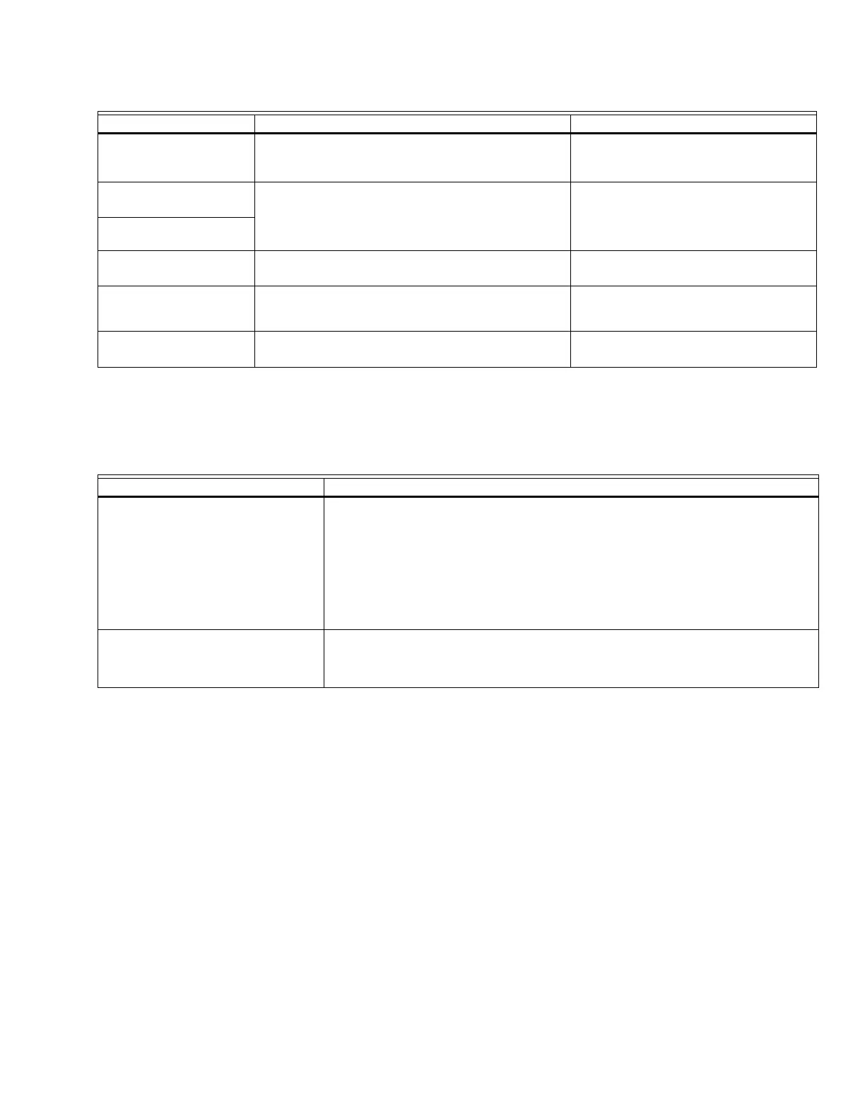
Table 1. Recommended Wire Sizes and Part Numbers.
a
The KDM, Data ControlBus™ Module (for remote mounting or communications) or Communication Interface Control-
Bus™ Module must be wired in a daisy chain configuration, (1(a)-1(a), 2(b)-2(b), 3(c)-3(c)). The order of interconnection
of all the devices listed above is not important. Be aware that modules on the closest and farthest end of the daisy chain
configuration string require a 120 ohm (1/4 watt minimum) resistor termination across terminals 1 and 2 of the electri-
cal connectors for connections over 100 feet (30.5 meters).
Table 2. Recommended Grounding Practices.
Final Wiring Check
1. Check the power supply circuit. The voltage and fre-
quency tolerance must match those of the relay
module. (A separate power supply circuit can be
required for the relay module.) Add the required dis-
connect means and overload protection.
2. Check all wiring circuits and complete the Static
Checkout in Table 5 or 6 before installing the relay
module on the subbase.
3. Install the relay module.
4. Restore power to the panel.
Mounting EC/RM7830A;
EC/RM7850A Relay Module
1. Mount the relay module vertically on the Q7800
Subbase, or mount horizontally with the knife blade
terminals pointing down. Select a location on a wall,
burner or electrical panel to mount the subbase. For
all CE device installations the subbase must be
mounted inside of an approved electrical cabinet
where access is restricted.
2. Be sure to allow adequate clearance for servicing,
installation and removal of the relay module, KDM,
flame amplifier, flame amplifier signal voltage
probes, electrical signal voltage probes and
electrical connections.
a. Allow an additional 2 in. (51 mm) below the relay
module for the flame amplifier mounting.
b. Allow an optional 3 in. (76 mm) minimum on
both sides of the relay module for electrical sig-
nal voltage probes.
Application Recommended Wire Size Recommended Part Numbers
Line Voltage Terminals
14, 16, or 18 AWG (0.75, 1.5 or 2.5 mm
2
) copper
conductor, 600 volt insulation, moisture-resistant
wire.
TTW60C, THW75C, THHN90C.
Keyboard Display
Module KDM
a
22 AWG (0.34 mm
2
) two-wire twisted pair with
ground, or five-wire.
Belden 8723 shielded cable or
equivalent.
Data ControlBus™
Module
Remote Reset Module
22 AWG (0.34 mm
2
) two-wire twisted pair, insulated
for low voltage.
—
Communications
Interface ControlBus™
Module
22 AWG (0.34 mm
2
) two-wire twisted pair with
ground.
Belden 8723 shielded cable or
equivalent.
13 Vdc full wave rectified
transformer power input
18 AWG (0.75 mm
2
) wire insulated for voltages and
temperatures for given application.
TTW60C, THW75C, THHN90C.
Ground Type Recommended Practice
Earth ground (subbase and relay
module)
1. Use to provide a connection between the subbase and the control panel of
the equipment. Earth ground must be capable of conducting enough cur-
rent to blow the 15A fuse (or breaker) in the event of an internal short circuit.
2. Use wide straps or brackets to provide minimum-length, maximum-surface
area ground conductors. If a leadwire must be used, use 14 AWG (2.5 mm
2
)
copper wire.
3. Make sure that mechanically tightened joints along the ground path are free
of nonconductive coatings and protected against corrosion on mating sur-
faces.
Signal Ground (KDM, Data
ControlBus™ Module,
Communications Interface
ControlBus™ Module)
Use the shield of the signal wire to ground the device to the signal ground terminal
3(c) of each device. Connect the shield at both ends of the daisy chain to earth
ground.
 Loading...