15 65-0086—2
Assembly
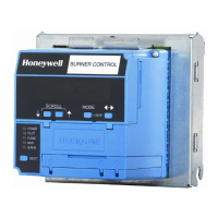
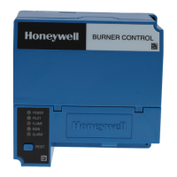
RM7895A,B,C,D
ASSEMBLY
Fig. 9—Electrical panel installation.
MOUNTING RM7895
NOTE: For installation dimensions, see Figs. 1 or 2.
RELAY MODULE MOUNTING
1. Mount the RM7895 vertically, see Figs. 9 or 10, or
mount horizontally with the knife blade terminals pointing
downward. When mounted on the Q7800A, the RM7895
must be in an electrical enclosure, see Fig. 9.
2. Select the location in the electrical enclosure. Be sure
to allow adequate clearance for servicing, installation and
removal of the RM7895, Dust Cover, flame amplifier, flame
amplifier signal voltage probes, electrical signal voltage
probes and electrical connections.
a. Allow an additional two inches below the RM7895
for the flame amplifier mounting.
b. Allow an optional three-inch minimum to both sides
of the RM7895 for electrical signal voltage probes.
c. Allow an optional two inches above the RM7895C,D
for access to the Run/Test Switch.
3. Make sure no subbase wiring is projecting beyond
the terminal blocks. Tuck wiring in against the back of the
subbase so it does not interfere with the knife blade termi-
nals or bifurcated contacts.
4. Mount the RM7895 by aligning the four L shaped
corner guides and knife blade terminals with the bifurcated
contacts on the wiring subbase and tightening the two screws
securely without deforming the plastic.
IMPORTANT: Install the RM7895 with a plug-in motion
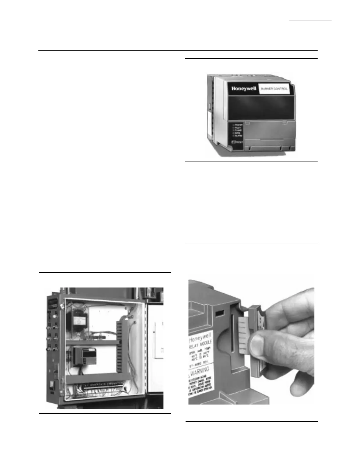
rather than a hinge action. Fig. 11—ST7800 Purge Card installation.
INSTALLING ST7800 PURGE CARD
1. Remove the Dust Cover, Keyboard Display Module,
DATA CONTROLBUS MODULE™or Extension Cable
Assembly.
2. Remove the current ST7800 from the RM7895 by
pulling upward on the plastic support cover, see Fig. 11.
3. Make sure that the ST7800 selected has the desired
timing.
4. Insert the Purge Card into the opening of the RM7895
compartment, see Fig. 11.
Fig. 10—Wall or burner installation.
 Loading...